Light projection apparatus, light condensing unit, and light emitting apparatus
a light emitting apparatus and light projection technology, which is applied in lighting and heating apparatus, planar/plate-like light guides, instruments, etc., can solve the problems of reducing the efficiency of light use (laser light), affecting the efficiency of light use, so as to reduce the amount of laser light absorbed, suppress damage, and reduce hardness
- Summary
- Abstract
- Description
- Claims
- Application Information
AI Technical Summary
Benefits of technology
Problems solved by technology
Method used
Image

Examples
first embodiment
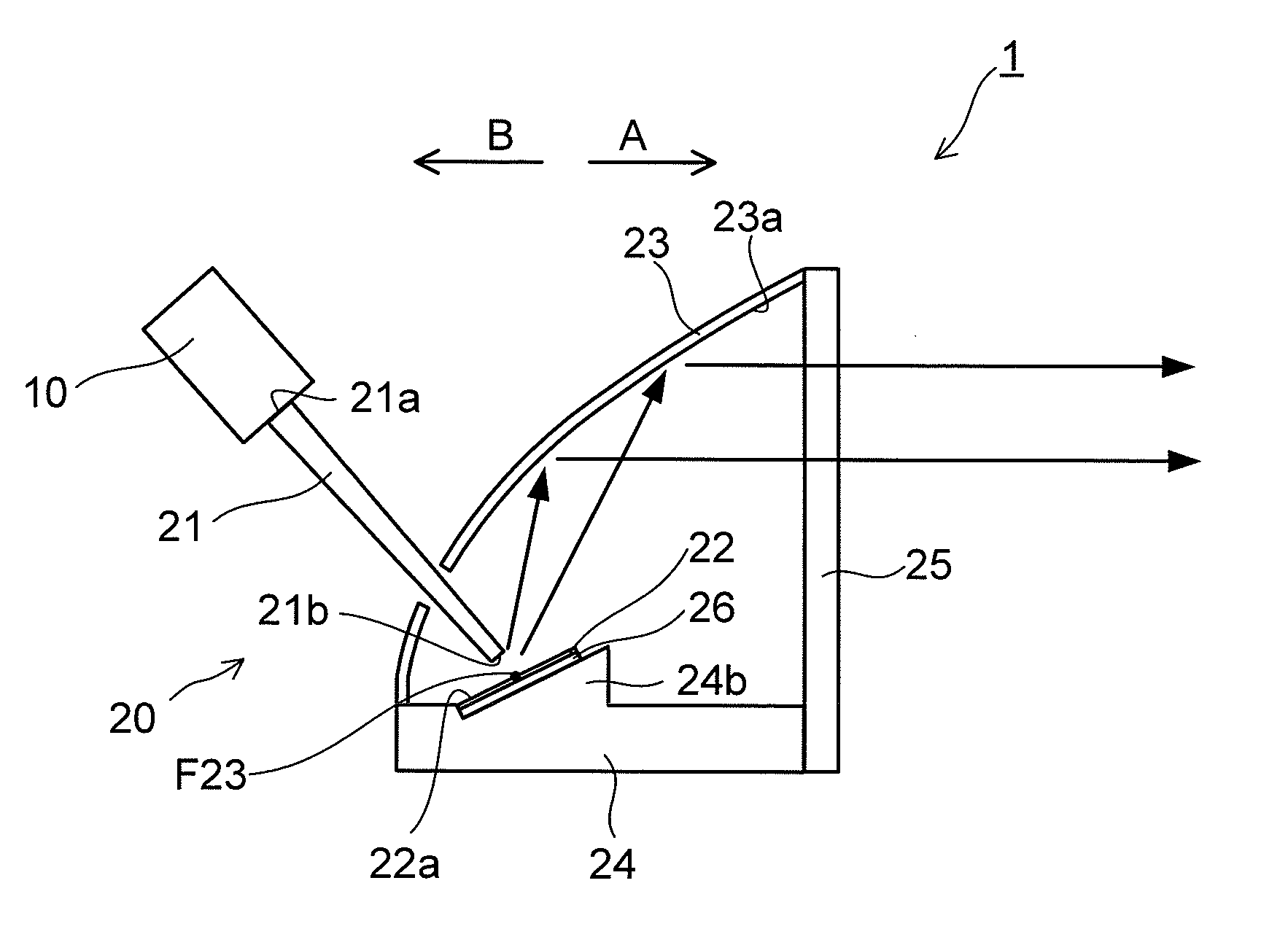
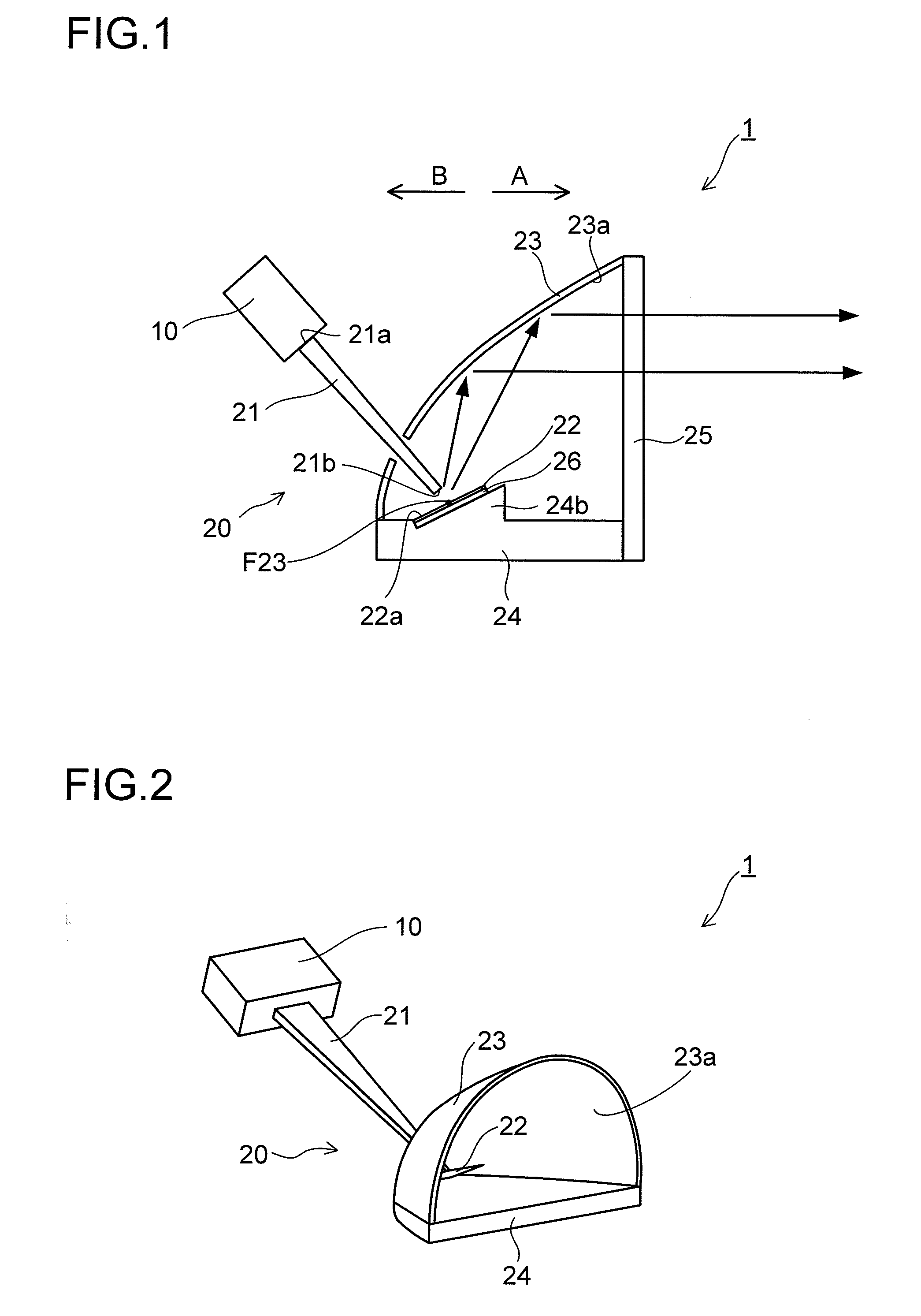
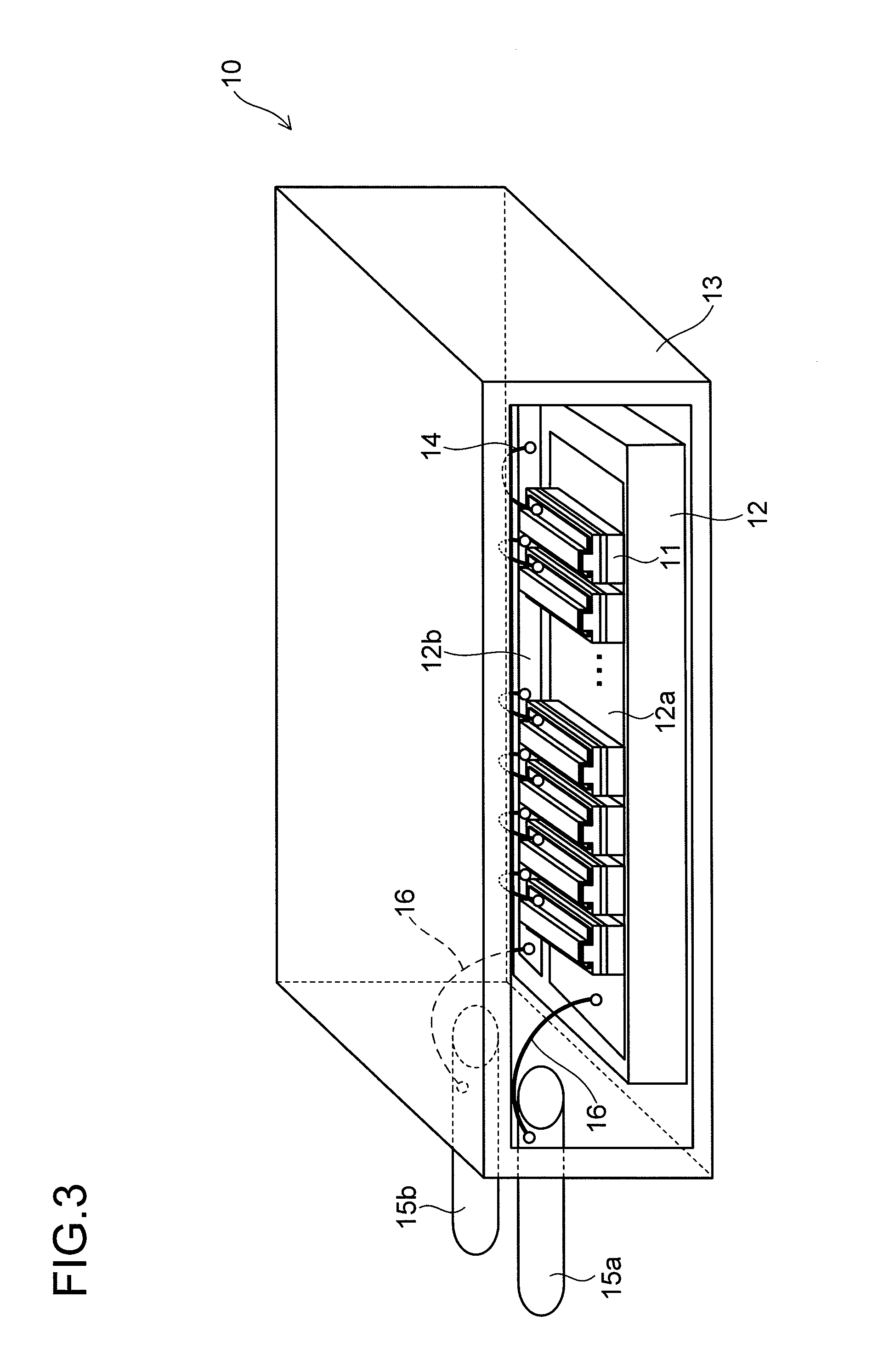
[0153]First, with reference to FIGS. 1 to 23, the structure of a light projection apparatus 1 according to a first embodiment of the invention will be described. For the sake of simple illustration, not all semiconductor laser elements 11 are always illustrated.
[0154]The light projection apparatus 1 according to the first embodiment of the invention is used as a headlamp for illuminating ahead of, for example, an automobile or the like. As shown in FIGS. 1 and 2, the light projection apparatus 1 is provided with a laser generating device 10 which functions as a laser light source (exciting light source) and a light projecting unit 20 which, by using the laser light emanating from the laser generating device 10, projects light in a predetermined direction (direction A). In FIG. 2, for the sake of easy understanding, a fitting portion 24b, a filter member 25, and a support plate 26, which will be described later, of the light projecting unit 20 are omitted.
[0155]As shown in FIG. 3, th...
second embodiment
[0191]As a second embodiment, with reference to FIG. 25, a description will now be given of a case where, unlike in the first embodiment described above, the fluorescence emanating from the rear face (the face opposite from the irradiated face 22a) of the fluorescent member 22 is reflected on the reflecting member 23.
[0192]In a light projection apparatus 101 according to the second embodiment of the invention, as shown in FIG. 25, a light projection unit 120 includes a light condensing member 21, a fluorescent member 22, a reflecting member 23, and a subsidiary reflecting member 127.
[0193]The fluorescent member 22 has a thickness of about 0.1 mm to about 1 mm, and the irradiated face 22a and the rear face of the fluorescent member 22 are formed in the same size as the light exit face 21b of the light condensing member 21. The fluorescent member 22 is fixed on the light exit face 21b of the light condensing member 21. Thus, as in the first embodiment described previously, the fluores...
third embodiment
[0199]As a third embodiment, with reference to FIGS. 26 to 29, a description will be given of a case where, unlike in the first and second embodiments described above, the light exit face 21b of the light condensing member 21 is formed in an elongate hexagonal shape.
[0200]In the light condensing member 21 in this embodiment, as shown in FIG. 26, the light entrance face 21a and the light exit face 21b are formed in an elongate hexagonal shape. Specifically, the light entrance face 21a has a height (H21a) of about 3 mm and a width (W21a) of about 15 mm. The light exit face 21b has a height (H21b) of about 2 mm and a width (W21b) of about 6 mm. The top face 21c and the bottom face 21d have, at their light exit face 21b side end, a width (W21c) of about 2 mm.
[0201]Thus, when laser light is shone onto the fluorescent member 22, the irradiated region S on the fluorescent member 22 appears as shown in FIG. 27, and the length (Lc) of the irradiated region S in direction C is three times or ...
PUM
 Abstract
Description
Claims
Application Information
 - R&D
- Intellectual Property
- Life Sciences
- Materials
- Tech Scout
- Unparalleled Data Quality
- Higher Quality Content
- 60% Fewer Hallucinations
Browse by: Latest US Patents, China's latest patents, Technical Efficacy Thesaurus, Application Domain, Technology Topic, Popular Technical Reports.
© 2025 PatSnap. All rights reserved.Legal|Privacy policy|Modern Slavery Act Transparency Statement|Sitemap|About US| Contact US: help@patsnap.com