Air-driven hydraulic pump with pressure control

Inactive Publication Date: 2012-12-13
YAN MI +1
View PDF12 Cites 5 Cited by
  • Summary
  • Abstract
  • Description
  • Claims
  • Application Information

AI Technical Summary

Benefits of technology

[0013]According to another embodiment of the invention, a hydraulic buffer is provided with an air-driven hydraulic injection pump. The hydraulic buffer decreases pressure drops associated with suction strokes in which compressed air is released from the pump.

Problems solved by technology

As a result, fluctuations in compressed air supply pressure affect both reciprocating rate and driving pressure.
Also, in the pressing stroke, compressed air expands and results in pressure drop.

Method used


Image

  • Air-driven hydraulic pump with pressure control
  • Air-driven hydraulic pump with pressure control
  • Air-driven hydraulic pump with pressure control

Examples


Embodiment Construction

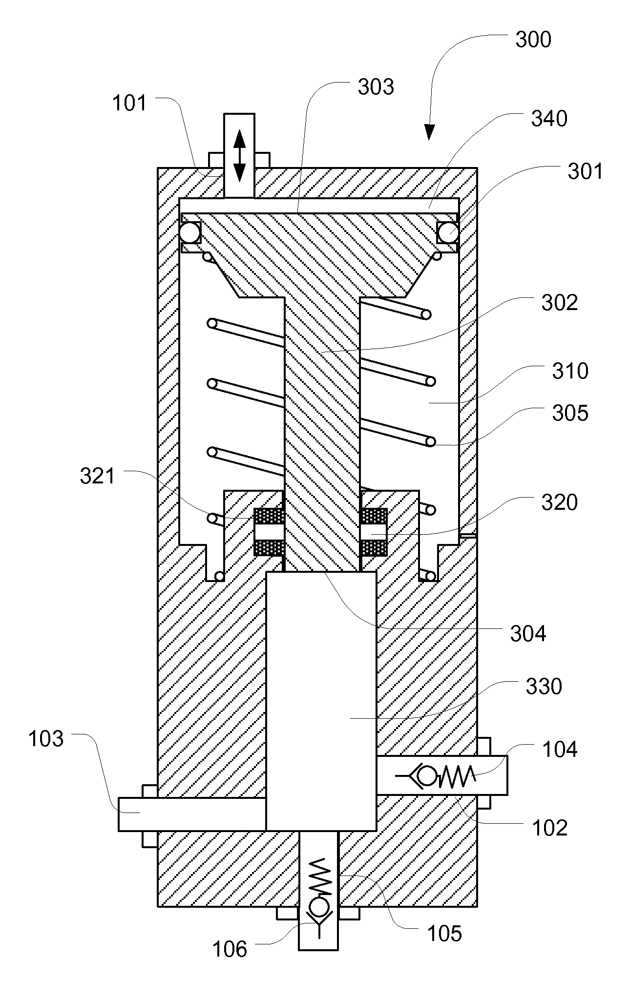
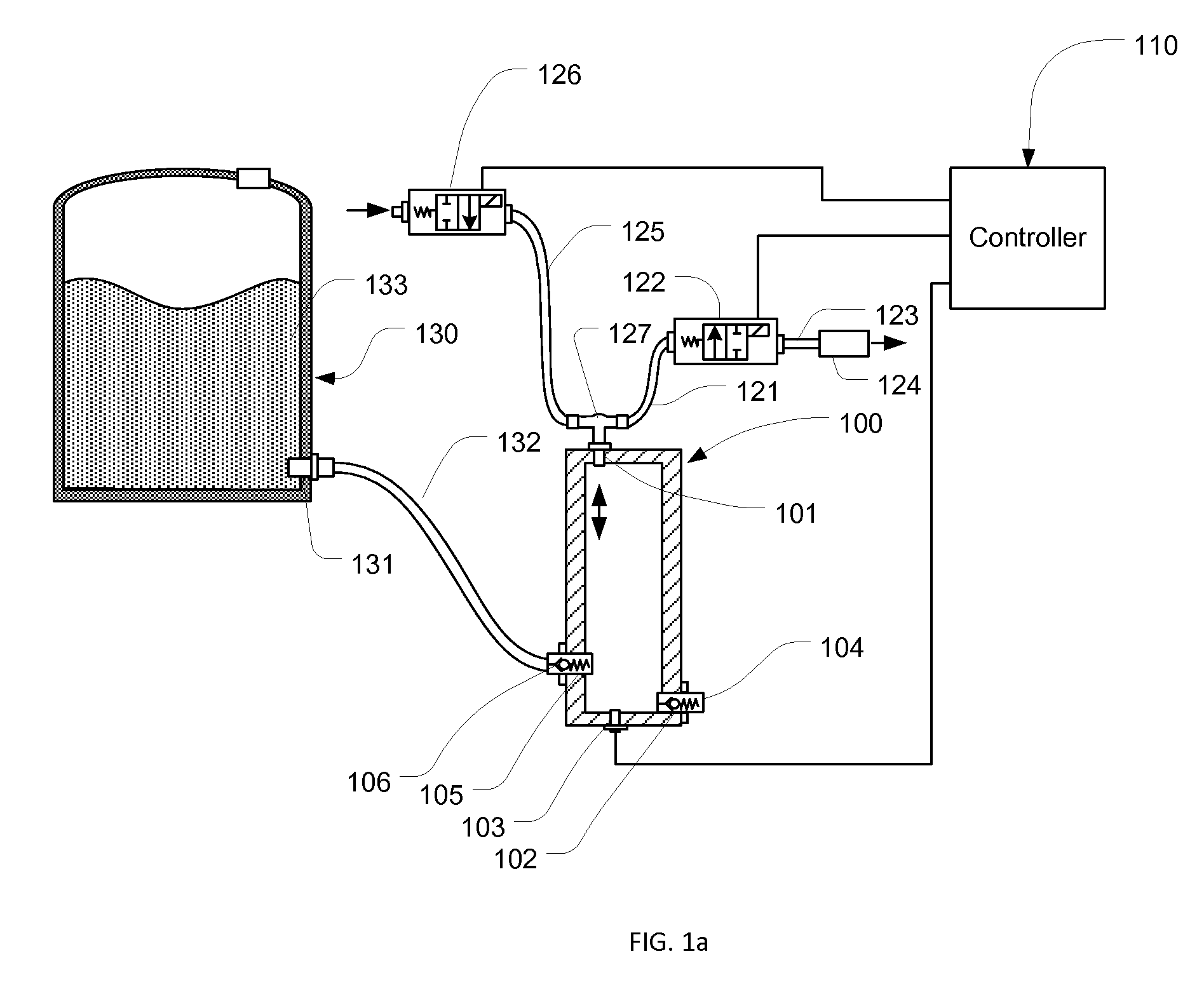
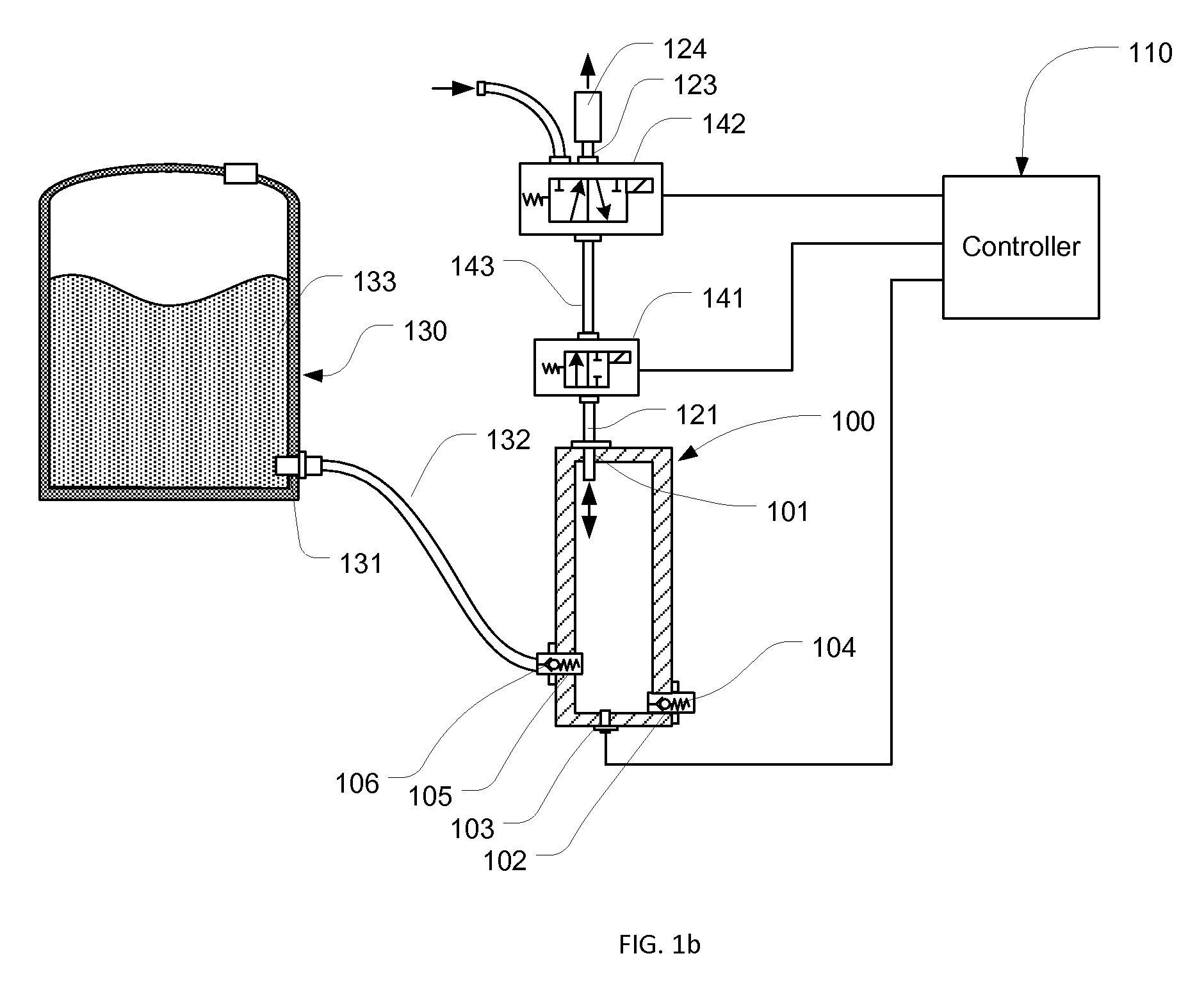
[0023]Referring to FIG. 1a, a pump 100 includes a gas port 101, a liquid inlet port 105, a liquid outlet port 102, and a pressure sensor 103. Through a liquid passage 132, the liquid inlet port 105 is fluidly connected to a port 131 of a liquid tank 130, which contains a fluid 133. Inside the inlet port 105, a check valve 106 only allows liquid to flow from the liquid tank 130 to the pump 100. Fluid in the pump 100 flows out through the liquid outlet port 102, which has a check valve 104 included, while pressure inside the pump is measured by the pressure sensor 103 and the sensing value is sent to a controller 110. The gas port 101 of the pump 100 is fluidly coupled to the outlet of a two-way solenoid valve 126 through a Tee connector 127 and an air passage 125, and the inlet of the solenoid valve 126 is connected to a compressed air supply (not shown in FIG. 1a). The Tee connector 127 is also fluidly connected to the inlet of another two way solenoid valve 122 through an air passa...


PUM


Abstract

A hydraulically driven pump with driving pressure controlled within a predetermined range. The hydraulically driven pump has a driving-fluid port fluidly coupled to a compressed air source and ambient, a driven-fluid inlet port fluidly connected to a tank, and a driven-fluid outlet port. A pressure sensor is used for providing sensing values indicative to the driving pressure in the hydraulically driven pump, and the driving pressure is controlled in closed loop by releasing and filling air through the driving-fluid port. The hydraulically driven pump has a suction stroke, in which driven fluid is refilled into the pump, and a pressing stroke, in which driven fluid is pressed out. A hydraulic buffer is used to provide driving pressure during a suction stroke and two hydraulically driven pumps can work alternately in providing continuous pressure control.

Description

CROSS-REFERENCE TO RELATED APPLICATIONS[0001]Not ApplicableSTATEMENT REGARDING FEDERALLY SPONSORED RESEARCH OR DEVELOPMENT[0002]Not ApplicableREFERENCE TO SEQUENCE LISTING, A TABLE, OR A COMPUTER PROGRAM LISTING COMPACT DISC APPENDIX[0003]Not ApplicableFIELD OF THE INVENTION[0004]This present application claims priority from U.S. provisional application No. 61 / 520,630 having the same title as the present invention and filed on Jun. 13, 2011.[0005]This invention relates to pumps, and more particularly, to hydraulic injection pumps used in injecting fluid into a vessel, the pressure inside which is controlled within a predetermined range.BACKGROUND OF THE INVENTION[0006]Air-driven hydraulic pumps use compressed air to drive reciprocating actions in delivering pressurized liquid. With a stepped piston having its large diameter side contacting compressed air in an air cylinder and small diameter side driving liquid in a high pressure injection cylinder, an air-driven hydraulic pump is a...

Claims


Application Information

Patent Timeline
IPC IPC(8): F04B19/20
CPCF04B19/20F04B9/12
Inventor YAN, MIQI, BAOHUA
Owner YAN MI
Why Eureka
Try Eureka