Gas flow control arrangement

Inactive Publication Date: 2012-03-29
ALSTOM TECH LTD
View PDF17 Cites 17 Cited by
  • Summary
  • Abstract
  • Description
  • Claims
  • Application Information

AI Technical Summary

Benefits of technology

[0023]According to another embodiment, at a desired distance downstream with respect to the flow of process gas from the first and second expanded screens is a third expanded screen and a fourth expanded screen with each of their second peripheral edges positioned at a point relatively the same within the duct. The opposed first peripheral edges of each of the third and fourth expanded screens are positioned apart from one another. The first peripheral edges are upstream with respect to the flow of process gas from the second peripheral edges. According to an embodiment, the first peripheral edges of each of the third and fourth expanded screens are arranged so as to abut opposing interior walls of the duct. Thereby, a zone between the two pairs of expanded screens may be formed. The zone may be provided as a mixing zone wherein gas particles are mixed to provide an even distribution of particles and gas temperatures. Such an arrangement of expanded screens may provide for a decreased pressure drop through the gas flow control arrangement over that of prior arrangements.
[0024]According to another aspect of the invention, an exhaust gas cleaning system for an industrial process plant such as a fossil-fueled power plant or a waste incineration plant is provided. The system comprises a gas cleaning device, a hollow inlet duct fluidly connected to the gas cleaning device to channel a flow of exhaust/process gases to the gas cleaning device, and a hollow outlet duct fluidly connected to the gas cleaning device to channel flowing process gases cleaned in the gas cleaning device out from the gas cleaning device. The system is characterized in that a gas flow control arrangement is positioned in the inlet duct. Thereby, a system may be provided that may mix process gases prior to the process gases flowing into the gas cleaning device. Well mixed process gases with an even distribution of particles and temperatures may enhance the performance of the cleaning device and extend the working lifetime of the cleaning device. Further, sufficient process gas mixing may make the cleaning process in the cleaning device more tolerant to variations in process gas conditions.
[0025]In one aspect, the exhau

Problems solved by technology

Especially in large, process plant-sized ducts, a long expanse of duct correlates to a considerable amount of material and capital expense.
Further, such a static mixer causes an undesirable pressure drop.
System pressure drops are

Method used


Image

  • Gas flow control arrangement
  • Gas flow control arrangement
  • Gas flow control arrangement

Examples


Embodiment Construction

[0040]The present invention is described more fully hereinafter with reference to the accompanying drawings, in which preferred embodiments of the invention are shown. This invention may, however, be embodied in many different forms not limited to the embodiments set forth herein. The embodiments provided herein are intended to fully convey the spirit and scope of the invention to those skilled in the art. In the drawings, like numbers refer to like elements.

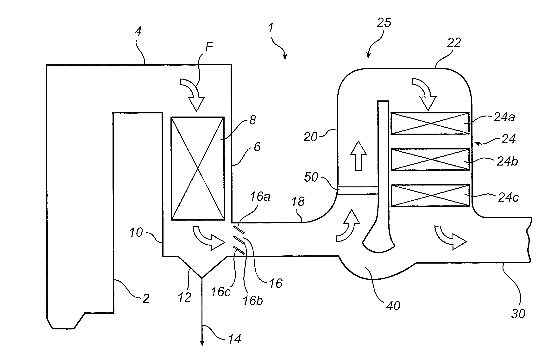
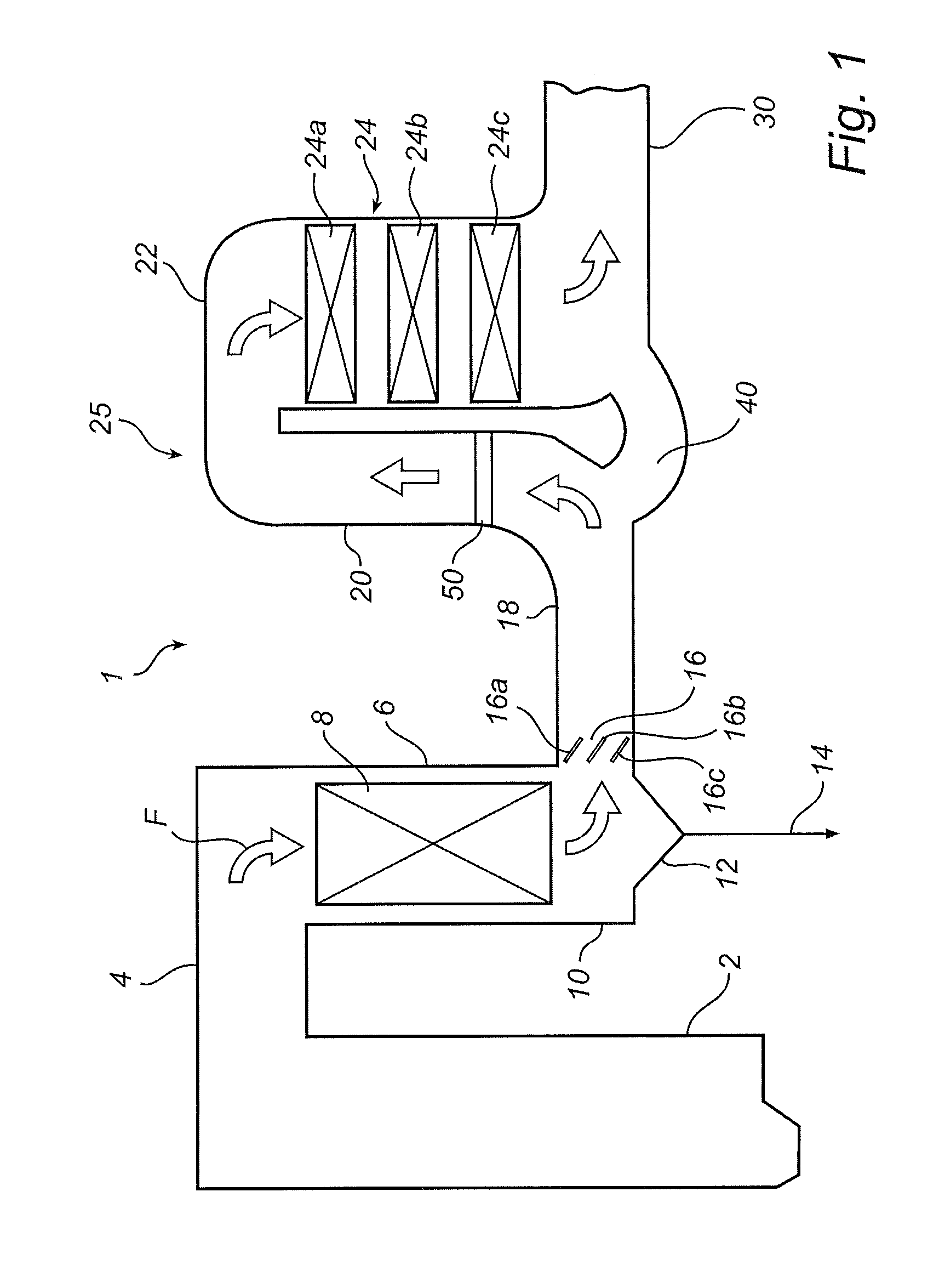
[0041]FIG. 1 illustrates a power station 1. The power station 1 has a boiler 2, in which a fuel, such as coal, oil or waste, is burnt while in contact with supplied air. Process / flue gases F and particles formed in the burning process within the boiler flow through duct 4 to a flue gas cooler 6, also referred to as an economizer. In the flue gas cooler 6, heat is extracted from the flue gases as they flow downward through a package of tubes 8. An exterior surface of tubes within the package of tubes 8 are in direct contact with ...


PUM

PropertyMeasurementUnit
Angleaaaaaaaaaa
Angleaaaaaaaaaa
Flow rateaaaaaaaaaa

Abstract

A gas flow control arrangement for use in an exhaust gas cleaning system, comprising a duct (20) through which flue gases flow from a first end (20a) toward a second end (20b). The duct is configured to have a longitudinal expanse between its first end and its second end, and a gas flow control device (80) arranged therein. The gas flow control device further comprises at least one expanded screen (81, 82, 83, 84) arranged at an angle within the duct to distribute gas flow. A method for controlling gas flow in an exhaust gas cleaning system is also described.

Description

TECHNICAL FIELD[0001]The present disclosure relates to a gas cleaning system, such as a catalytic reduction system or an electrostatic precipitator system, for use in an industrial process plant, such as a fossil-fueled power plant or a waste incineration plant. More particularly, the present disclosure relates to a gas flow control arrangement for use in an exhaust gas cleaning system. The subject gas flow control arrangement comprises: a duct through which exhaust gases flow from a first end toward a second end with a gas flow control device arranged therein.BACKGROUND[0002]In the combustion of a fuel, such as coal, oil, peat, waste, etc. in an industrial process plant, such as a fossil-fuelled power plant, a hot process gas is generated, such process gas containing, among other components, dust particles, sometimes referred to as fly ash, and nitrogen oxides. The dust particles are often removed from the process gas by means of a dust removal device, such as an electrostatic prec...

Claims


Application Information

Patent Timeline
IPC IPC(8): F15D1/00B01D53/86B01F23/10
CPCB01D53/86B01D53/8625B01D2251/2062B01F2005/0638B01F5/0616B01F5/0693B01F2005/0622B01F3/02Y10T137/794Y10T137/0318B01F23/10B01F25/43171B01F25/4315B01F25/431973B01F25/4523
Inventor HJELMBERG, ANDERS ERIKTABIKH, ALI MUSTAPHA
Owner ALSTOM TECH LTD
Why Eureka
Try Eureka