
Communication apparatus, communication method and remote monitoring system

Inactive Publication Date: 2012-12-13
HITACHI LTD
View PDF0 Cites 12 Cited by
  • Summary
  • Abstract
  • Description
  • Claims
  • Application Information

AI Technical Summary

Benefits of technology

[0005]Network congestion that is experienced by an apparatus occurs when the rate at which signals are input to the apparatus has exceeded the rate at which signals are output from the apparatus. If the apparatus has a buffer, signals are stored into the buffer at a rate corresponding to a difference between the output signal rate and the input signal rate and the signals will delay in proportion to the amount of signals stored in the buffer. The priority control suggested in Patent Document 1 and others alleviates the influence of delay caused by the buffer by preferentially processing a packet that requires a low delay.
[0008]In order to address the problems noted above, the present invention is intended to provide a communication apparatus, communication method, and remote monitoring system that allow for a stable reduction in delay for packets that require a low delay even in a case where a network undergoing a large fluctuation is used in the remote monitoring system.
[0014]a rate control block that determines a transmission data rate of second information depending on the delay time, so that the transmission data rate of second information should become smaller when the delay time is larger; and
[0020]determining a transmission data rate of second information depending on the delay time, so that the transmission data rate of second information should become smaller when the delay time is larger; and
[0029]a rate control block that determines a transmission data rate of second information depending on the delay time, so that the transmission data rate of second information should become smaller when the delay time is larger; and
[0031]According to the aspects of the present invention, it is possible to provide a communication apparatus, communication method, and remote monitoring system that allow for a stable reduction in delay for packets that require a low delay even in an environment where the communication rate largely fluctuates, for example, in a case where radio communication is used on a network physical layer of the remote monitoring system.

Problems solved by technology

Network congestion that is experienced by an apparatus occurs when the rate at which signals are input to the apparatus has exceeded the rate at which signals are output from the apparatus.
Therefore, that technique can alleviate the influence of the buffer on an IP layer, but cannot alleviate the influence of the buffer on a lower layer.
However, there is such a problem that this large buffer accumulates signals, which may cause a large delay in some situations, and this delay cannot be alleviated by the priority control according to, e.g., the technique described in Patent Document 1.

Method used


Image

  • Communication apparatus, communication method and remote monitoring system
  • Communication apparatus, communication method and remote monitoring system
  • Communication apparatus, communication method and remote monitoring system

Examples


first embodiment

1. First Embodiment

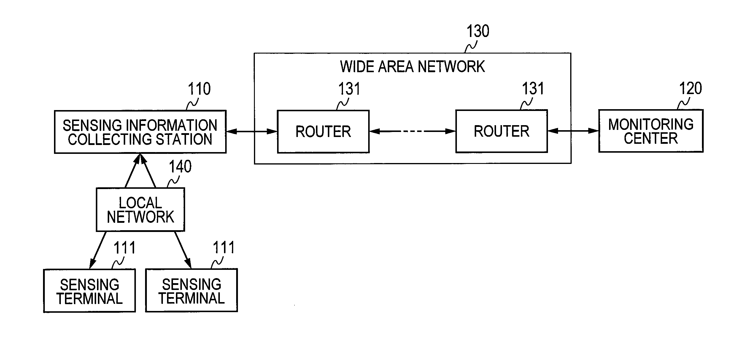
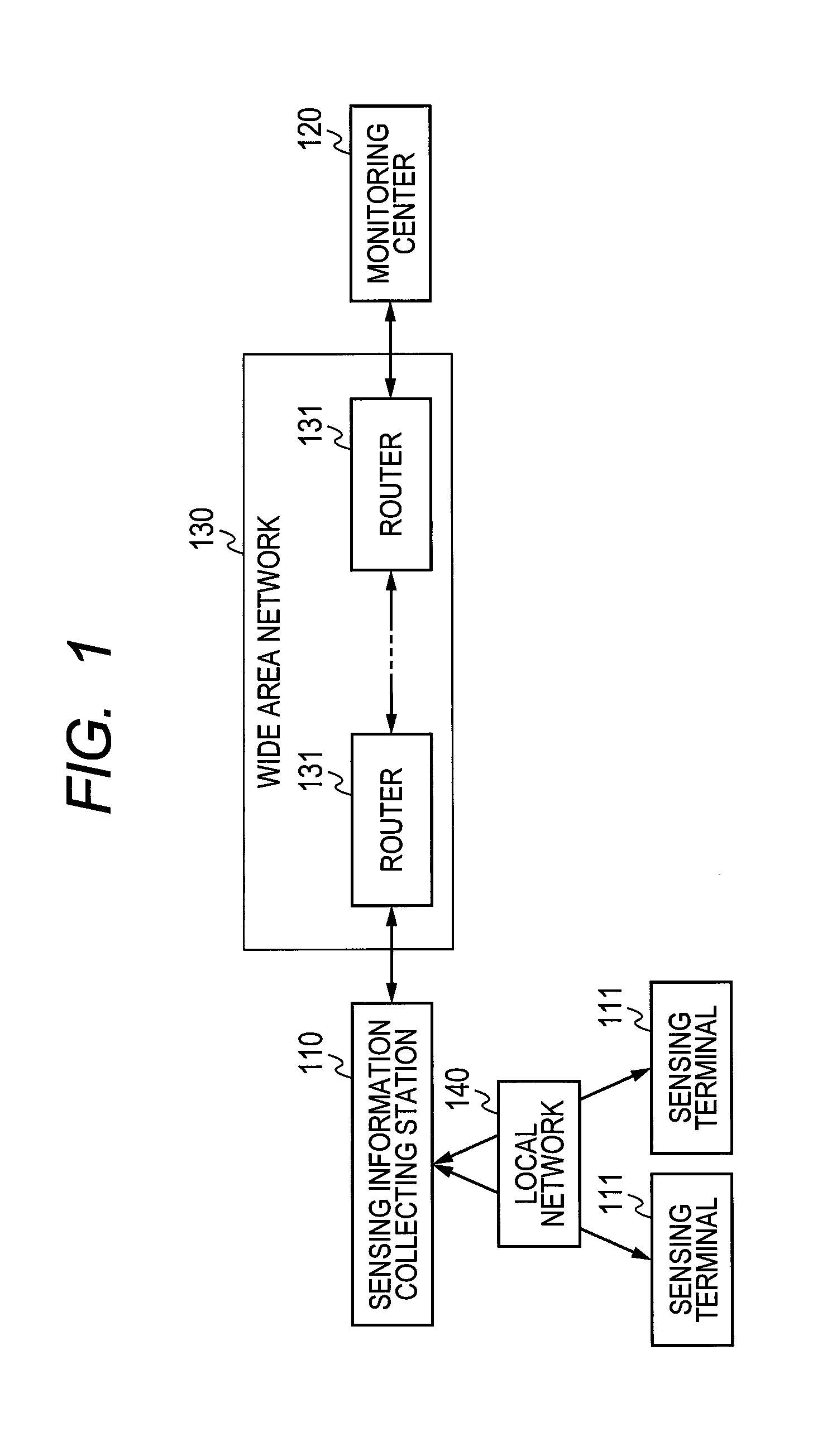
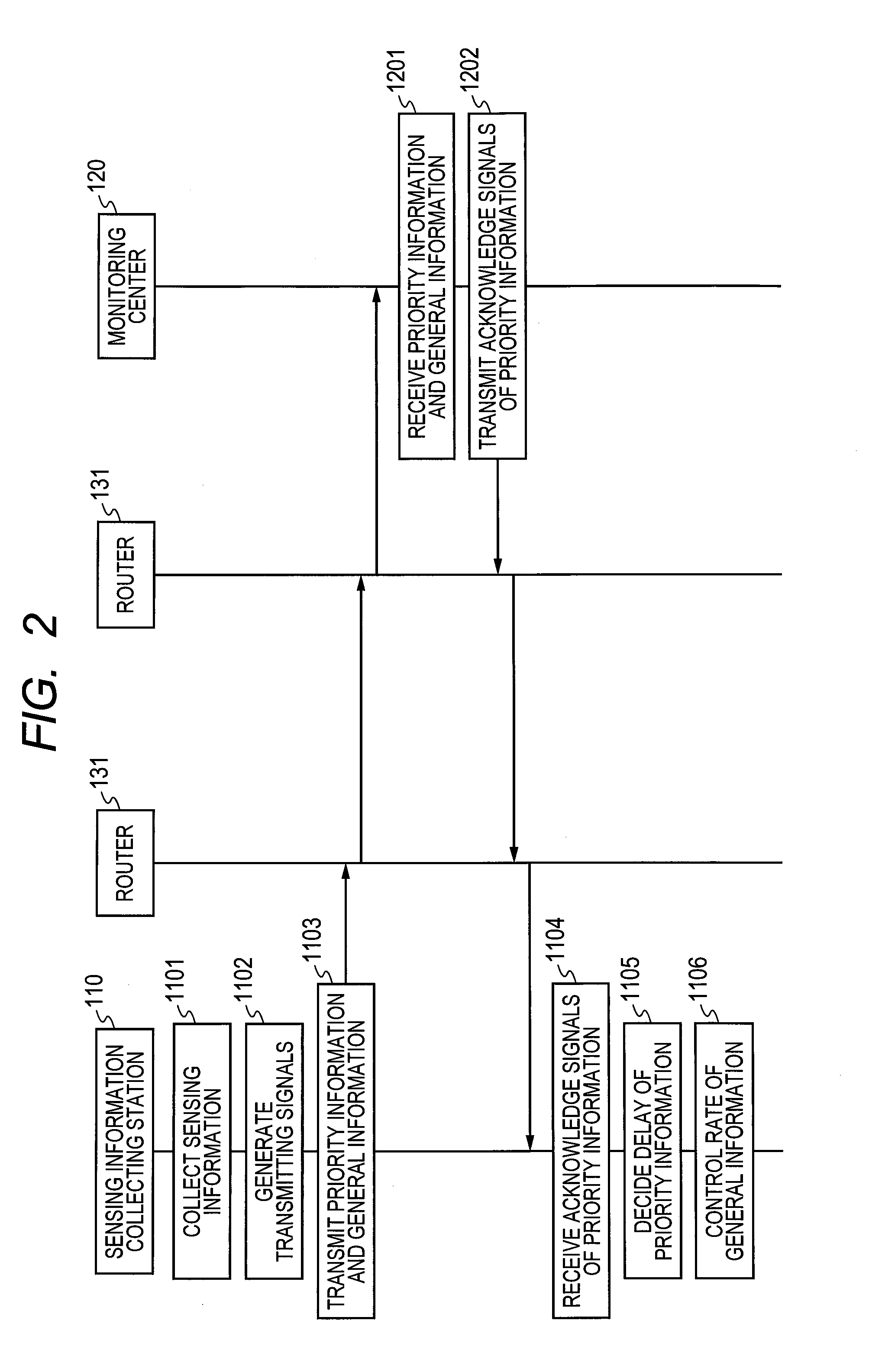
[0052]FIG. 1 depicts an overall structural diagram of a remote monitoring system.

[0053]The remote monitoring system according to embodiments described herein includes a sensing information collecting station (network communication apparatus, communication apparatus, or sensing information collecting station) 110 and a monitoring center (monitoring apparatus) 120 which are connected via, for example, a wide area network 130 and one or more sensing terminals 111 which are connected to the sensing information collecting station 110 via a local network 140. The wide area network 130 includes one or more routers (forwarding apparatuses or communication apparatuses) 131.

[0054]A sensing terminal 111 has a sensor function and a local network communication function. A sensing terminal 111 makes a measurement using the sensor function and sends sensor sensing information obtained as a result of the measurement to the sensing information collecting station 110 via the local ...

second embodiment

2. Second Embodiment

[0097]In the foregoing first embodiment, an example of the case where the sensing information collecting station 110 determines a network delay time based on a response signal to priority information that the sensing information collecting station 110 transmitted to the monitoring center 120 and the sensing information collecting station 110 performs general information rate control has been described. On the other hand, it is also possible that, without the use of a response signal in determining a network delay time, the monitoring center 120 determines a network delay time and sends it to the sensing information collecting station 110 and the sensing information collecting station 110 performs general information rate control.

[0098]FIG. 6 shows an example of a sequence in the remote monitoring system according to a second embodiment. The sensing information collecting station 110 first acquires, collects, and stores sensor sensing information sent from one or ...

third embodiment

3. Third Embodiment

[0118]In the foregoing second embodiment, an example where the monitoring center 120 determines a network delay time and the sensing information collecting station 110 performs rate control of general information. This is an example of determining a delay time for the entire network from the sensing information collecting station 110 to the monitoring center 120 as the network delay time. On the other hand, in a case where a network delay time fluctuates prominently in a partial section of the network, it is also possible to determine a network delay time after priority information and general information has passed the section and perform rate control of general information before priority information and general information pass the section. For example, any apparatus may determine a network delay time and another apparatus may perform rate control of general information; this manner of implementation can also produce the same effect.

[0119]FIG. 8 shows an exampl...


PUM


Abstract

In a remote monitoring system including a monitoring center, a sensing information collecting station, and one or more sensing terminals, the sensing information collecting station collects measurement results measured by the sensing terminals, classifies the collected measurement results into priority information and general information, and transmits priority information and general information to the monitoring center. The monitoring center transmits response information to received priority information to the sensing information collecting station. The sensing information collecting station estimates network condition from a delay time based on the response information and decreases the transmission rate of general information when the estimated network condition is more congested. Thereby, even if the network condition fluctuates, desired information such as statistical information on measurement results and measurement results meeting a predetermined condition is communicated stably at low delay.

Description

CLAIM OF PRIORITY[0001]The present application claims priority from Japanese patent application JP 2011-128012 filed on Jun. 8, 2011, the content of which is hereby incorporated by reference into this application.FIELD OF THE INVENTION[0002]The present invention relates to a communication apparatus, communication method, and remote monitoring system and, particularly, to a communication apparatus, communication method, and remote monitoring system using a network operating in a fluctuating communication environment for radio communication or the like.BACKGROUND OF THE INVENTION[0003]Lately, a remote monitoring system is widespread in which measurement results measured by various sensors are monitored at a monitoring center via a network. To carry out remote monitoring, it is not only necessary to communicate measurement results measured by sensors, which may come to a large amount of data, but also a stable reduction in communication delay is needed so that the monitoring center can...

Claims


Application Information

Patent Timeline
IPC IPC(8): G06F15/173
CPCH04L1/0002Y02B60/31H04L1/0088H04L1/0018Y02D30/50
Inventor TAMAKI, SATOSHITAKADA, MAYYUNOKI, SHOJI
Owner HITACHI LTD
Features
  • Generate Ideas
  • Intellectual Property
  • Life Sciences
  • Materials
  • Tech Scout
  • Unparalleled Data Quality
  • Higher Quality Content
  • 60% Fewer Hallucinations
Learn More