
Modular nut plates with closed nut assemblies

a technology of modular nut plates and assemblies, which is applied in the direction of threaded fasteners, mechanical devices, fastening means, etc., can solve the problems of brackets unsuitable for installation in workpiece openings, and achieve the effect of enhancing dimensional stability and reducing part counts

Active Publication Date: 2012-12-20
FATIGUE TECH
View PDF0 Cites 23 Cited by
  • Summary
  • Abstract
  • Description
  • Claims
  • Application Information

AI Technical Summary

Benefits of technology

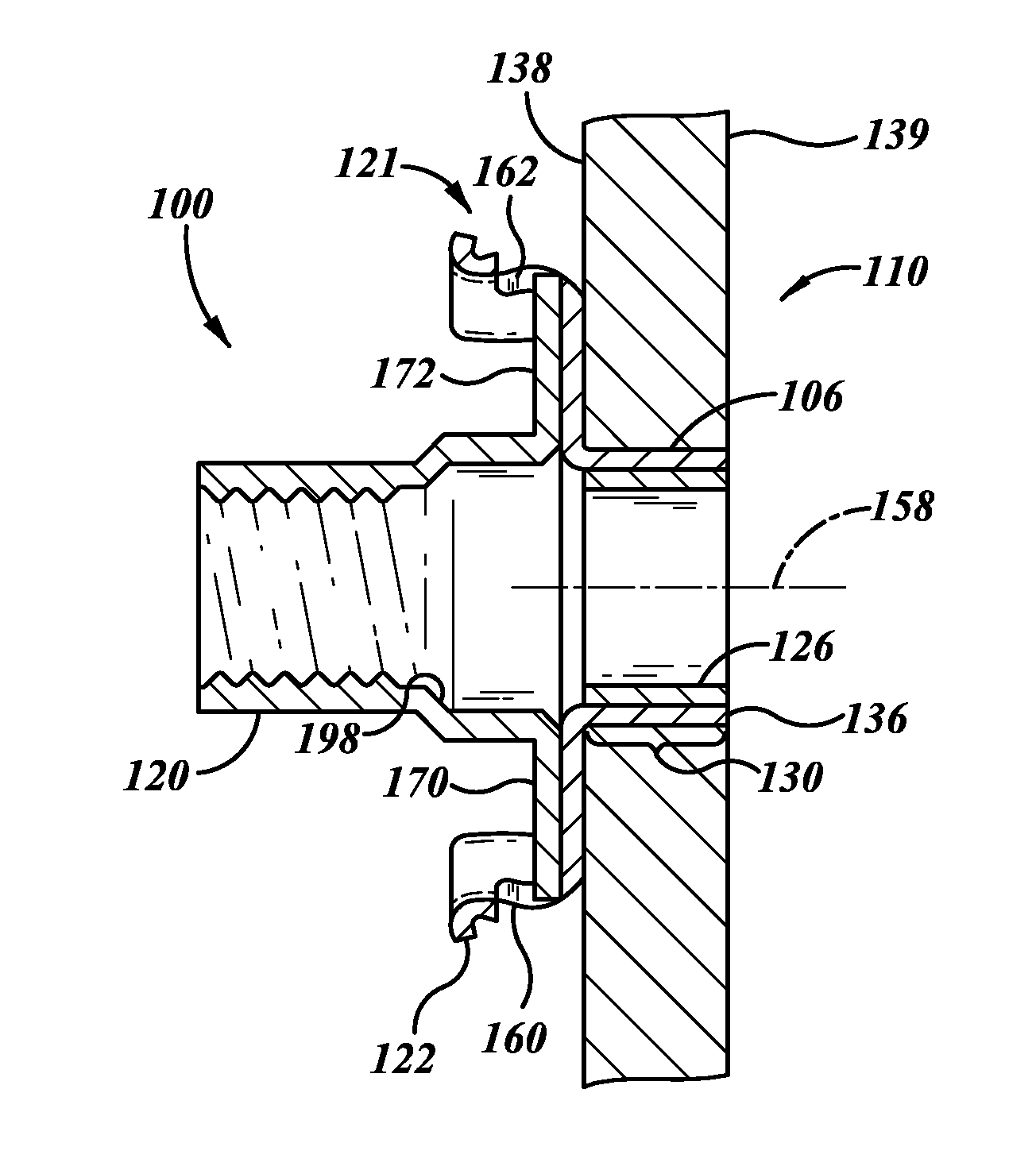
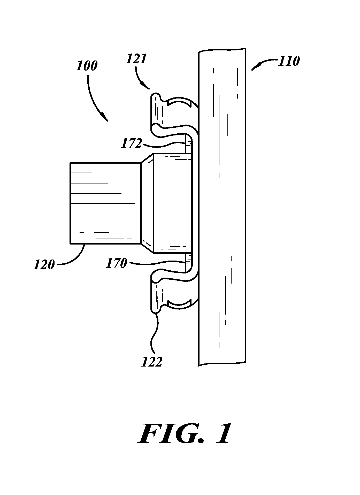
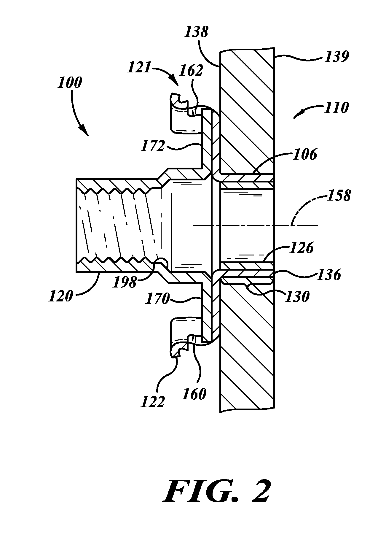
[0008]The sealed dome nut assembly can have a plastic-to-metal interface between the cap retainer and dome cap that can reduce corrosion, wear, arcing (e.g., due to lightening strikes), and the like. The cage assembly can also provide a plastic-to-metal interface with the cap retainer. In certain embodiments, the dome cap includes a plastic main body made by an injection molding process. The retainer body can comprise mostly metal by weight and can be deformed against the dome cap to securely hold the dome cap within the cap retainer.
[0041]A nut plate assembly may be summarized as including a cap, a retainer assembly, or other components with dielectric properties that provide resistance to arcing, for example, when subjected to high electrical current loads. High electrical current loads can be associated with lightning strikes or electrical malfunctions. The nut plate assembly can reduce or eliminate damage associated with such high electrical current loads. In certain embodiments, the cap is made of a polymer, such as TORLON®. The problem of lightning strikes is particularly significant if the nut plate is installed near to or in a wall of a fuel tank because arcing, sparks, or burning material could cause an explosion. The nut plate assembly can thus be installed near to or in fuel tanks.

Problems solved by technology

Unfortunately, the one-piece sleeve has a fixed longitudinal length rendering the bracket unsuitable for installation in workpiece openings having longitudinal lengths that are significantly different from the length of the sleeve.

Method used


Image

  • Modular nut plates with closed nut assemblies
  • Modular nut plates with closed nut assemblies
  • Modular nut plates with closed nut assemblies

Examples


Embodiment Construction

[0105]In the following description, certain specific details are set forth in order to provide a thorough understanding of various embodiments of the invention. However, one skilled in the art will understand that the invention may be practiced without these details. The assemblies and processes disclosed herein can be used to couple together a desired number of components. The components can include, without limitation, workpieces, connectors, mounting components, and the like. The terms “proximal” and “distal” are used to describe the illustrated embodiments and are used consistently with the description of non-limiting exemplary applications. The terms proximal and distal are used in reference to the user's body when the user operates an installation system, unless the context clearly indicates otherwise.

[0106]Unless the context requires otherwise, throughout the specification and claims which follow, the word “comprise” and variations thereof, such as, “comprises” and “comprisin...


PUM

PropertyMeasurementUnit
Weightaaaaaaaaaa
Flow rateaaaaaaaaaa
Metallic bondaaaaaaaaaa

Abstract

A nut plate assembly includes a nut retainer and a bushing for expanding a tubular body of the retainer. The retainer assembly is used to cold work an opening of a workpiece in order to fix the nut retainer assembly relative to the workpiece. A nut can be snapped into the retainer. A method of installation includes passing a mandrel through the bushing to radially expand the bushing into a tubular body of the retainer. The tubular body is compressed between the workpiece and bushing as the bushing is displaced radially causing corresponding radial displacement of the tubular body. The expanded bushing applies pressure to the tubular body for a desired fit between the nut retainer and workpiece.

Description

CROSS REFERENCE TO RELATED APPLICATION[0001]This application claims the benefit under 35 U.S.C. §119(e) of U.S. Provisional Application No. 61 / 497,473, filed Jun. 15, 2011, where this provisional application is incorporated herein by reference in its entirety.BACKGROUND[0002]1. Technical Field[0003]This disclosure generally relates to modular nut plate assemblies with closed nut assemblies and methods of using the same.[0004]2. Description of the Related Art[0005]Rivetless nut plates are often installed into structural workpieces in order to couple components to the workpieces. Conventional nut plates may include a bracket and a nut coupleable to the bracket. The nut can receive an externally threaded component (e.g., a bolt or a screw) after the bracket has been secured to the workpiece. When the installed nut plate supports an attached component, a flat face of the bracket can bear against the workpiece to help distribute loads to the workpiece, thereby preventing excessive stress...

Claims


Application Information

Patent Timeline
IPC IPC(8): F16B37/04B21D39/00
CPCB21D39/04F16B17/006Y10T29/49938F16B37/044F16B37/043
Inventor ROSS, JAMES RYUNOSHINJOHNSON, TIMOTHY HOWARDGULICK, SCOTT HARLOW
Owner FATIGUE TECH
Learn More