
Sensor device and manufacturing method thereof

a manufacturing method and sensor technology, applied in the direction of devices using electric/magnetic means, acceleration measurement using interia forces, instruments, etc., can solve the problems of high cost of ceramic packaging, bottleneck in cost reduction of sensor devices, and affecting the accuracy of sensor devices, etc., to achieve high reliability

Inactive Publication Date: 2012-12-20
SEIKO EPSON CORP
View PDF17 Cites 17 Cited by
  • Summary
  • Abstract
  • Description
  • Claims
  • Application Information

AI Technical Summary

Benefits of technology

The invention provides a sensor device that solves problems of thickness and cost by using a thinner package and not requiring a separate mounting terminal. The sensor device includes a semiconductor device with electrodes, a frame-like fixing member, a vibrating piece, and a lid body. A lead wire is electrically connected to the electrodes and extends through the fixing member. An insulating resin layer may be used to prevent direct contact between the lead wire and the semiconductor device, reducing stress and damage. The sensor device can be manufactured with a reduced thickness and lower cost.

Problems solved by technology

However, the ceramic package has been generally expensive and becomes a bottleneck in cost reduction of the sensor device.
Further, there has been a problem that the thickness of the package is an obstacle to reduction in thickness of the sensor device.

Method used


Image

  • Sensor device and manufacturing method thereof
  • Sensor device and manufacturing method thereof
  • Sensor device and manufacturing method thereof

Examples


modified example 1

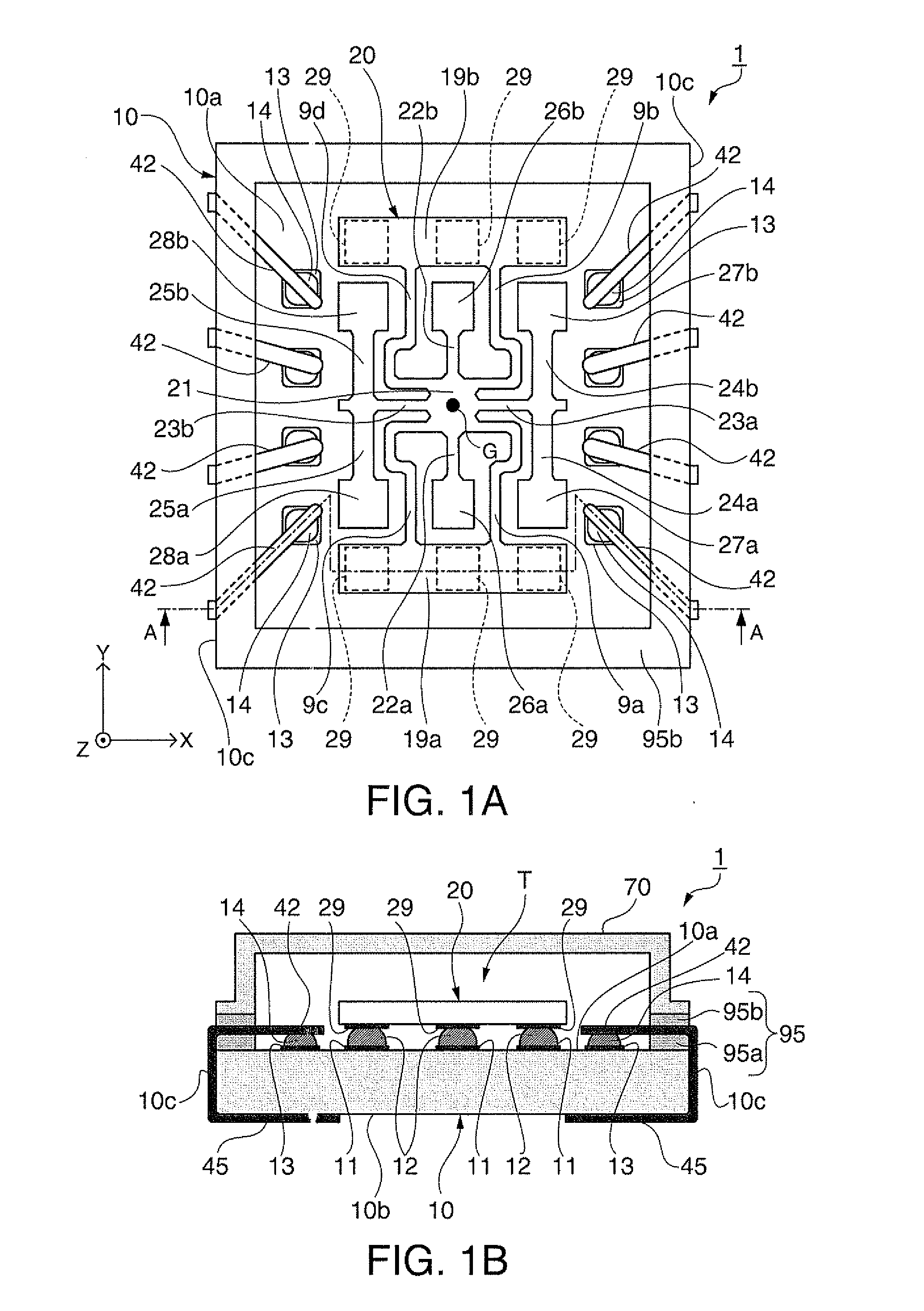
[0129]Modified example 1 of the sensor device will be explained using FIGS. 6A, 6B, and 7.

[0130]FIGS. 6A and 6B are schematic views showing a general configuration of modified example 1 of the sensor device, and FIG. 6A is a plan view as seen down from the vibration gyro element side (from above), and FIG. 6B is a sectional view of FIG. 6A. Further, FIG. 7 is a plan view schematically showing a flexible substrate on which the lead wires used for the sensor device of modified example 1 are formed.

[0131]Note that, in the explanation of modified example 1, the common parts with the embodiment have the same signs and their explanation will be omitted.

[0132]As shown in FIGS. 6A and 6B, a sensor device 101 of modified example 1 includes the IC chip 10, the vibration gyro element 20 held on the first surface 10a of the IC chip 10, the lid 70 bonded to cover the vibration gyro element 20 via the frame-like fixing member 95, and a flexible substrate 40 in which the lead wires 42 with one end...

modified example 2

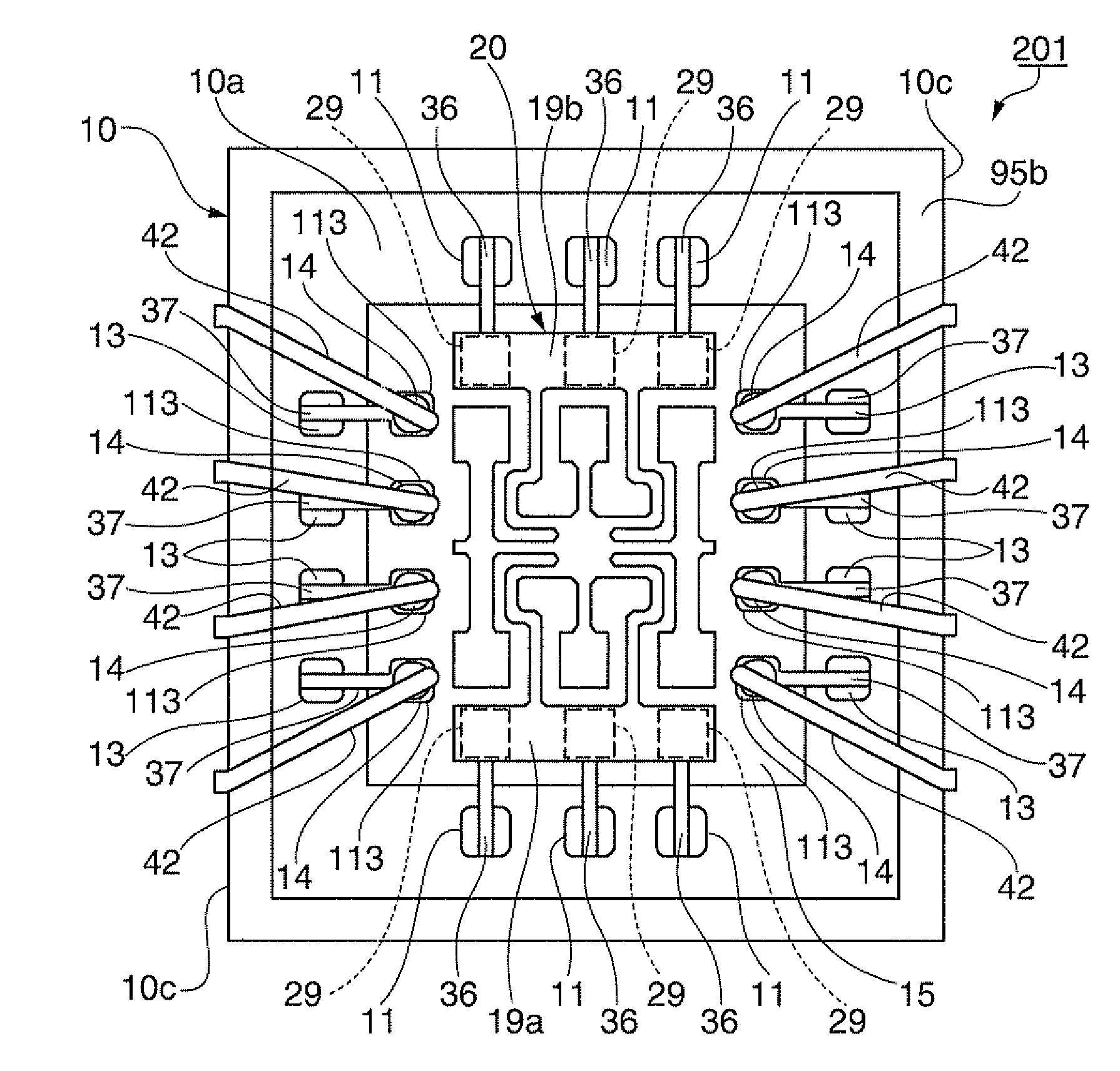
[0139]Next, modified example 2 of the sensor device will be explained using FIGS. 8A and 8B.

[0140]FIGS. 8A and 8B are schematic views showing a general configuration of modified example 2 of the sensor device, and FIG. 8A is a plan view as seen down from the vibration gyro element side (from above), and FIG. 8B is a sectional view of FIG. 8A.

[0141]Note that, in the explanation of modified example 2, the common parts with the embodiment have the same signs and their explanation will be omitted.

[0142]As shown in FIGS. 8A and 8B, a sensor device 201 of modified example 2 includes the IC chip 10, a stress relaxing layer 15 as an insulating resin layer provided on the first surface 10a of the IC chip 10, first relocation electrodes 111 provided on the stress relaxing layer 15 and electrically connected to the first electrodes 11, second relocation electrodes 113 electrically connected to the second electrodes 13, the vibration gyro element 20 electrically connected to the first relocatio...


PUM


Abstract

A sensor device includes an IC chip as a semiconductor device having a first electrode and a second electrode on a first surface, a frame-like fixing member provided to surround the first electrode and the second electrode, a vibration gyro element as a vibrating piece electrically connected to the first electrode, a lid as a lid body bonded to the first surface via the fixing member and forming a space that covers the vibration gyro element, and a lead wire electrically connected to the second electrode and extending through inside (between an IC-side fixing member and a lid-side fixing member in the embodiment) of the fixing member to outside of the space.

Description

[0001]The entire disclosure of Japanese Patent Application No. 2011-133937, filed Jun. 16, 2011 is expressly incorporated by reference herein.BACKGROUND[0002]1. Technical Field[0003]The present invention relates to a sensor device and a manufacturing method of the sensor device.[0004]2. Related Art[0005]In related art, in sensor devices that sense acceleration, angular velocities, or the like, a sensor device including a vibrating piece (sensor element) and a circuit element such as a drive circuit that drives the vibrating piece has been known.[0006]For example, Patent Document 1 (JP-A-2005-292079) discloses a gyro sensor as a sensor device including a vibration gyro element as a vibrating piece (gyro vibrating piece) and a semiconductor device as a circuit element.[0007]In the configuration of the gyro sensor described in Patent Document 1, the semiconductor device is fixed to a support substrate and electrically connected to a lead wiring part formed on the support substrate. Fur...

Claims


Application Information

Patent Timeline
Patent Type & Authority Applications(United States)
IPC IPC(8): G01P3/14H01L21/50
CPCH01L23/057G01C19/5783H01L2224/16225H01L2924/1461H01L2924/00
Inventor OTSUKI, TETSUYA
Owner SEIKO EPSON CORP
Learn More