Listening clamp for a vibroacoustic diagnosis tool used mainly in the automotive industry

Active Publication Date: 2012-12-20
PEZHO SITROEN AUTOMOBILS SA
View PDF5 Cites 2 Cited by
  • Summary
  • Abstract
  • Description
  • Claims
  • Application Information

AI Technical Summary

Benefits of technology

[0005]The goal is to provide a listening clamp for an acoustical vibration analysis tool, specifically a listening clamp which facilitates and improves, on the one hand, the acoustical vibration analysis performed during automotive

Problems solved by technology

In addition, significant loudness and level variations are induced by the positioning of the clamp on the structure to be analyzed.
The sensing quality is mediocre and makes diagnosis relatively difficult.
In addition, with this type of clamp there is a risk of short circuits, which can be particularly inconvenient, in particular when the clamps are used with hybrid vehicles.
Furthermore, the different types of applic

Method used


Image

  • Listening clamp for a vibroacoustic diagnosis tool used mainly in the automotive industry
  • Listening clamp for a vibroacoustic diagnosis tool used mainly in the automotive industry
  • Listening clamp for a vibroacoustic diagnosis tool used mainly in the automotive industry

Examples


first embodiment

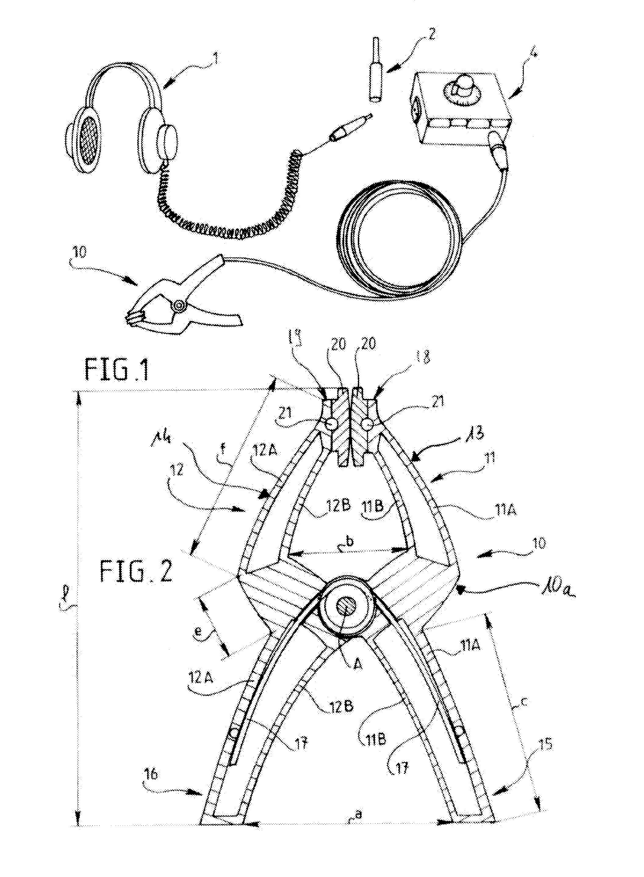
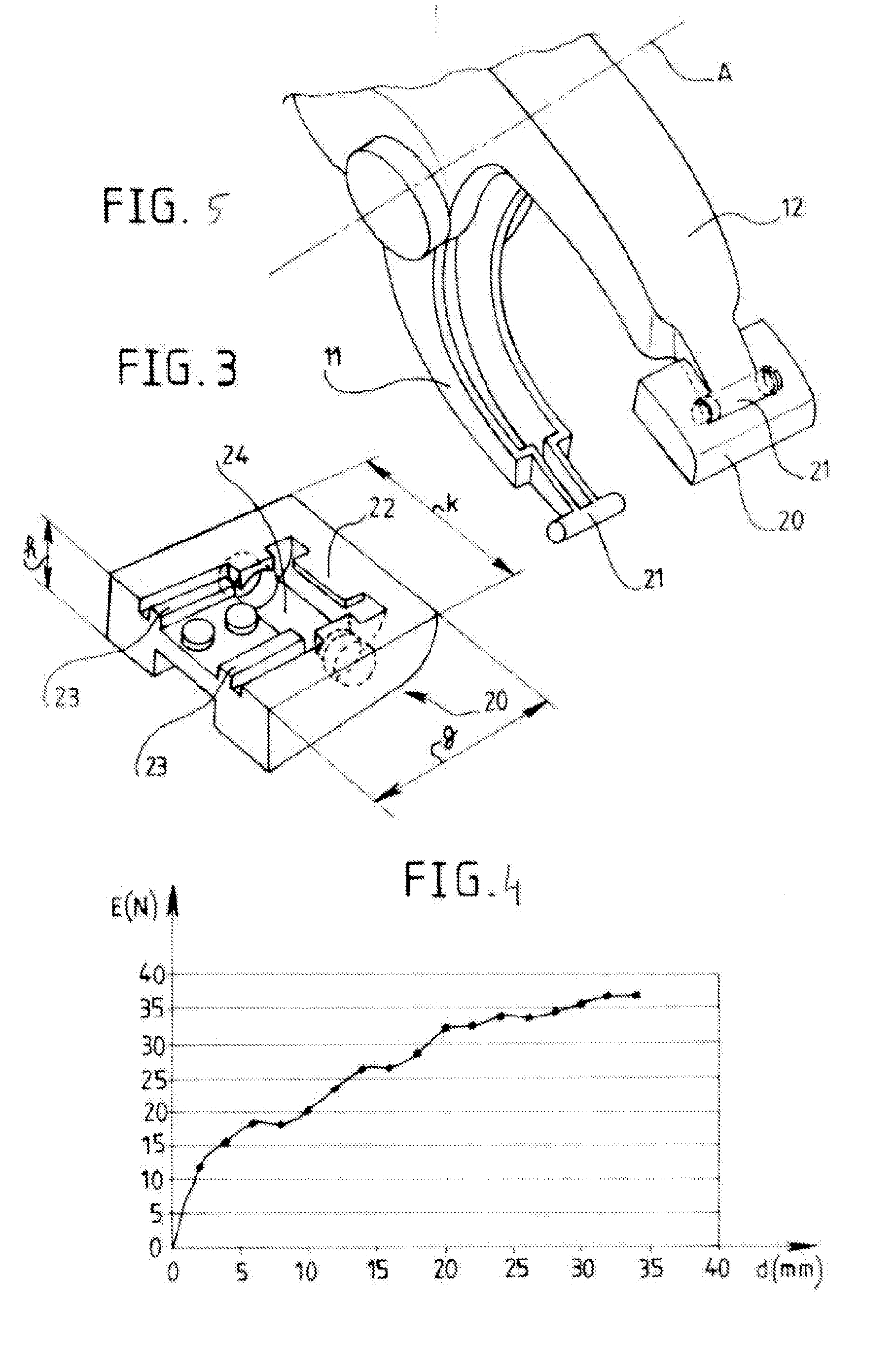
[0046]FIG. 5 illustrates more precisely the geometry of the distal extremities 18, 19 of the jaws 13, 14 at the location of pins 21. As illustrated in FIG. 3, pad 20 of the present invention comprises a cylindrical cavity 24 suitable for receiving pin 21 to form the articulation of pad 20 in body 10a of the listening clamp 10. Pin 21 is inserted in pad 20 by means of guides 23, and snaps in place in body 10a, and is retained in position due to tab 22 protruding above the cylindrical cavity 24.

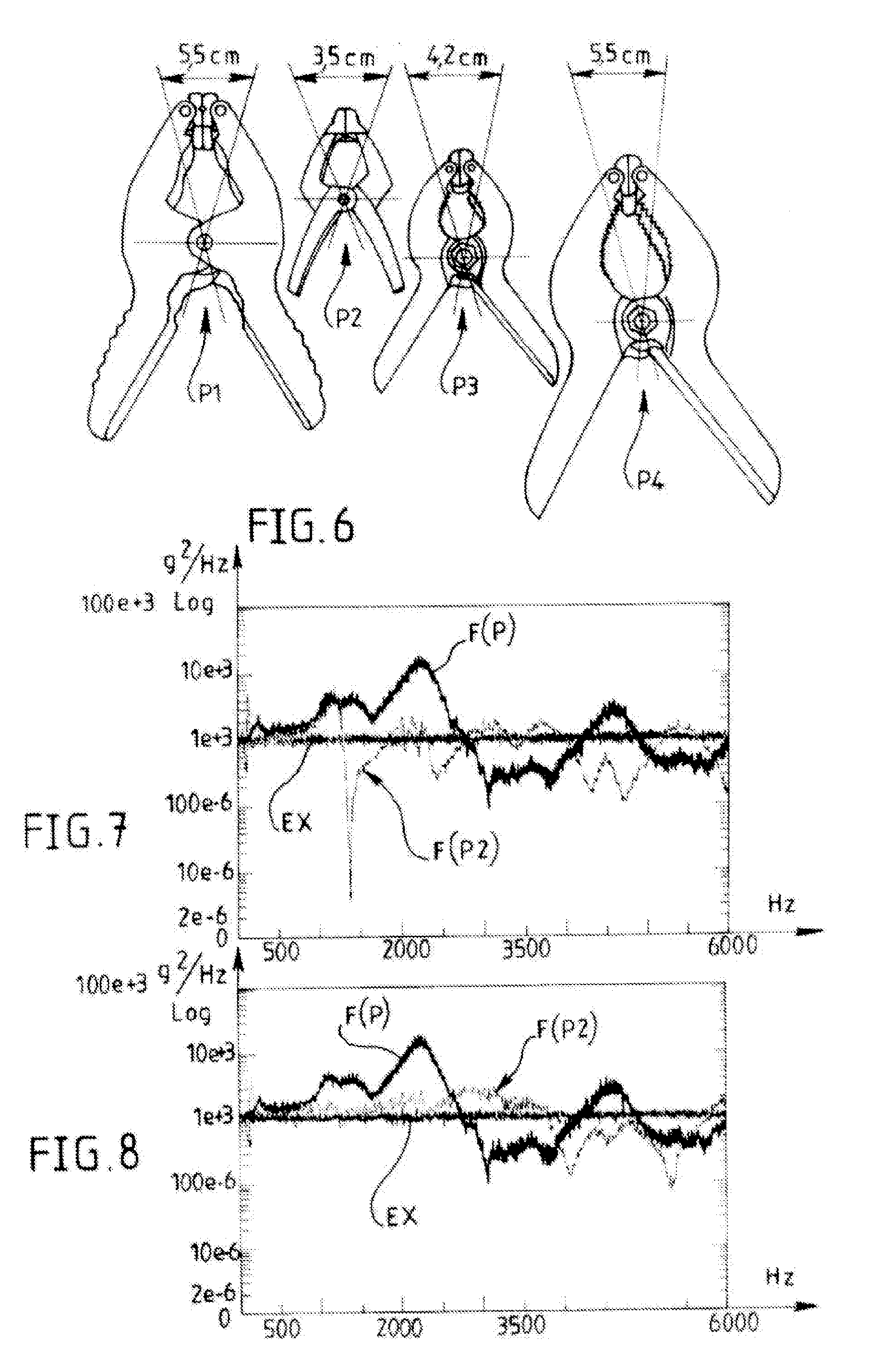
[0047]Vibration tests have been performed with the four types of listening clamps P1, P2, P3 and P4 shown in the drawing of FIG. 6. These four clamps, all made of plastic material in order not to cause electrical short circuits and risk for the users, have pads of hard plastic material mounted through the intermediary of swivel joints according to the above described example. The swivel joints of the pads provide, on the one hand, effective contact between the clamp and the part or assembly to ...

second embodiment

[0050]FIG. 9 illustrates a listening clamp 10 in which one of the pads 30 includes an accelerometer (not illustrated in this figure) which is connected by means of an electrical cable 28 to a plug 27 suitable for being plugged into selection box 4. The electrical cable 28 can have a separation at the extremity of a handle 16 in the form of a freely moving connector. In this way, listening clamp 10 can be easily mounted on the structure to be tested without being bothered by the cable 28. Cable 28 can pass through the body 10a and be attached to it by means of a glued joint.

[0051]The clamp can also have an accelerometer mounted in one jaw, and the corresponding pad has a ball which protrudes relative to one pad, whereby the ball serves as collector of vibrations from an element clamped between the jaws of the clamp.

[0052]As more precisely illustrated in FIG. 10, the pads 30 comprise a flat plate 32 oriented towards the clamping space and a mounting part 33 in which the cylindrical c...


PUM


Abstract

The invention relates to a clamp (10) which is used mainly in a vibroacoustic diagnosis tool during an automobile maintenance or after-sales assistance operation, including two hinged arms (11, 12), each comprising a jaw (13, 14) at one end and a handle (15, 16) at the other end. A pad (20) is mounted on each jaw (13, 14) via a ball-and-socket joint (21), such that the pad (20) ensures effective contact between the clamp (10) and the part being tested, and separates the body of the clamp from the listening part. The invention is useful in the field of motor vehicles. The invention is also useful in the vibroacoustic diagnosis of motor vehicles or motor vehicle subunits.

Description

CROSS-REFERENCE TO RELATED APPLICATIONS[0001]This application is the US National Stage under 36 U.S.C. §371 of International App. No. PCT / FR2010 / 052830 filed Dec. 20, 2010, and which claims priority to French App. Nos. 1050016 filed on Jan. 4, 2010 and 1050291 filed on Jan. 18, 2010, the contents of which (text, drawings and claims) are incorporated herein by reference.BACKGROUND[0002]The present invention relates to a listening clamp for an acoustical vibration analysis tool, and an acoustical vibration analysis tool using such a listening clamp. These objects are used in particular during maintenance operations or after-sales service of automotive vehicles.[0003]An acoustical vibration analysis tool comprises, in a known manner, a headset suitable for noisy environments, a microphone, four clamps for the detection of noise of a structural nature and a selector for immediate identification of the clamp nearest to the acoustical vibration phenomenon to be detected.[0004]A known type...

Claims


Application Information

Patent Timeline
IPC IPC(8): G01H1/12
CPCB25B5/06H04R1/46G01H1/12B25B5/163
Inventor RAGUENET, WILFRIDAUTIN, GREGORYAUBOIS, VALERIEPERONNET, CYRIL
Owner PEZHO SITROEN AUTOMOBILS SA
Why Eureka
Try Eureka