Measuring a length of movement of an elongate intraluminal device

a technology of intraluminal devices and lengths, applied in image enhancement, instruments, angiography, etc., can solve the problems of adding complexity, difficulty in maintaining a sterile environment and sterile equipment, etc., and achieve the effect of improving and facilitating

Active Publication Date: 2019-05-23
KONINKLJIJKE PHILIPS NV
View PDF0 Cites 2 Cited by
  • Summary
  • Abstract
  • Description
  • Claims
  • Application Information

AI Technical Summary

Benefits of technology

[0007]Hence, there may be a need to provide an improved and facilitated way of measuring a length of movement of an elongate intraluminal device.

Problems solved by technology

Such a measurement system generally relies on a specific instrument and wire set-up and thus adds to complexity.
Other systems require interaction of a medical professional with user interface devices, which presents difficulties with respect to maintaining a sterile environment and sterile equipment.

Method used


Image

  • Measuring a length of movement of an elongate intraluminal device
  • Measuring a length of movement of an elongate intraluminal device

Examples


Embodiment Construction

[0044]The following detailed description is merely exemplary in nature and is not intended to limit the application and uses. Furthermore, there is no intention to be bound by any expressed or implied theory presented in the preceding technical field, background, brief summary or the following detailed description.

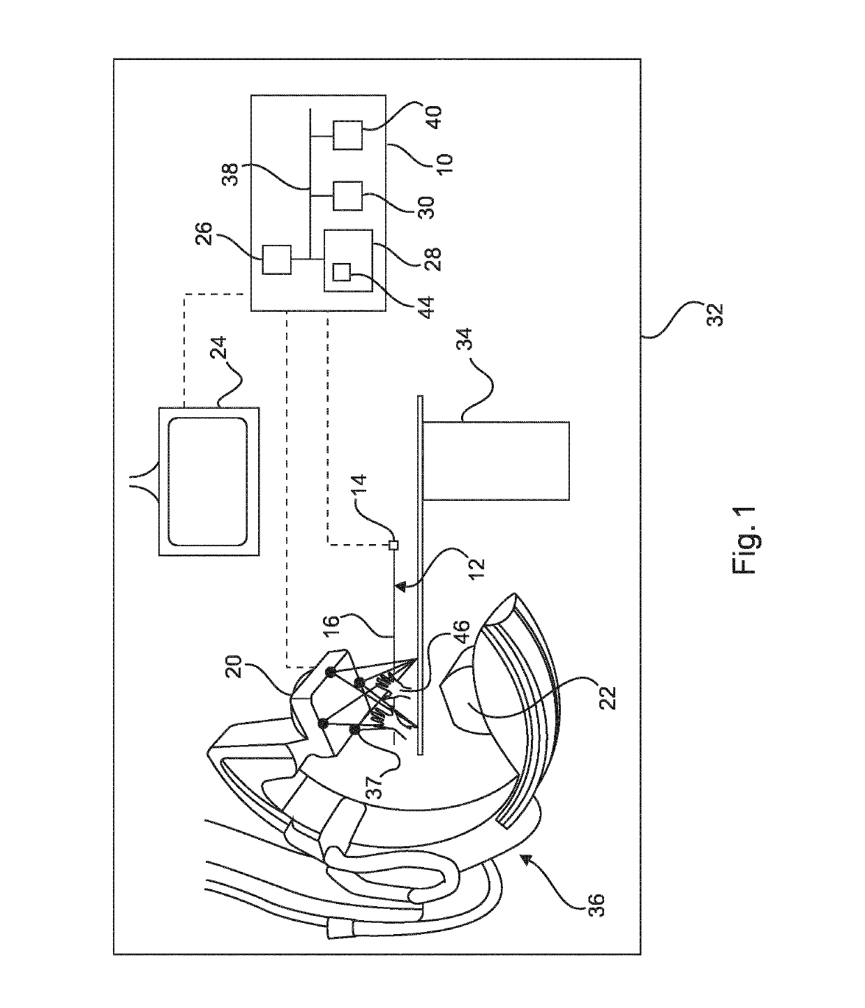
[0045]FIG. 1 is a schematic view of an imaging system 32 comprising an extracorporeal imaging machine 18, a processing and measurement system 10, a display unit 24, an elongate intraluminal device 12 and a patient support table 34.

[0046]The imaging machine 18 is configured for generating imaging data of a patient supported on a table 34. The imaging machine 18 comprises a detector 20 and an electromagnetic wave generator 22 such as an X-ray generator. The imaging machine 18 may be configured for MRI imaging, X-ray imaging and the like. The imaging machine 18 may be configured for angiogram imaging. Further, the imaging data may be configured for generating three-dimensiona...


PUM


Abstract

A measurement system for measuring a length of movement of an elongate intraluminal device. Cameras are included to obtain three dimensional video data of movement of an elongate intraluminal device by hand. The video data is processed to track the movement of the elongate intraluminal device in three dimensions to provide the length measurement of movement of the elongate intraluminal device.

Description

FIELD OF THE INVENTION[0001]The technical field generally relates to measuring a length of movement of an elongate intraluminal device, and more particularly to measuring a length of movement of a wire in an intravenous wire pullback method.BACKGROUND OF THE INVENTION[0002]Intravascular wire pullback measurements can be performed with a multitude of different sensors. These include pressure wires (iFR), intravascular ultrasound (IVUS), optical coherence tomography (OCT) and the like. Accurate registration of the wire based measurements with respect to the anatomy as it is visible from angiography projections profits from knowledge about the pullback length.[0003]A pullback wire may be connected to a measurement device during pullback. For example, US 2003 / 0187369 discloses an optical pullback sensor assembly that facilitates measuring displacement of a flexible elongate member, such as an ultrasound catheter probe that is inserted within a body. The optical pullback sensor assembly ...

Claims


Application Information

Patent Timeline
Patent Type & Authority Applications(United States)
IPC IPC(8): A61B34/20G06T7/246A61B90/00A61B5/11A61B5/06
CPCA61B34/20G06T7/246A61B90/37A61B5/1128A61B5/061A61B5/1114A61B5/1122G06T2207/10028G06T2207/10016G06T2200/04G06F3/017A61B2090/3937A61B5/749A61B2090/3735A61B2090/3782A61B2017/00207A61B2034/2055A61B2034/2065A61B2034/301A61B2090/064A61B2090/371A61B6/032A61B6/4441A61B6/504G06F3/0304
Inventor GRASS, MICHAELSENEGAS, JULIEN
Owner KONINKLJIJKE PHILIPS NV
Why Eureka
Try Eureka