Volume presentation for planning a location of an injection point

a volume presentation and injection point technology, applied in the field of visualizing a region of interest, can solve the problems of cumbersome slice presentation, inability to visualize all lesions/feeders, and inability to follow vessels in slice presentations, etc., to achieve the effect of improving and facilitating

Active Publication Date: 2020-01-16
KONINKLJIJKE PHILIPS NV
View PDF4 Cites 2 Cited by
  • Summary
  • Abstract
  • Description
  • Claims
  • Application Information

AI Technical Summary

Benefits of technology

[0012]Hence, there may be a need to provide an improved and facilitated way of visualizing imaging data for planning at least one location of an injection point.

Problems solved by technology

Following vessels in slice presentations can be cumbersome because of their discontinuity, which necessitates mental interpretation while browsing through the slices.
However, a highly detailed volume presentation provides an overload of visual information and can be processing intensive, whilst a lower detail presentation may not be able to visualize all lesions / feeders.

Method used


Image

  • Volume presentation for planning a location of an injection point
  • Volume presentation for planning a location of an injection point
  • Volume presentation for planning a location of an injection point

Examples


first embodiment

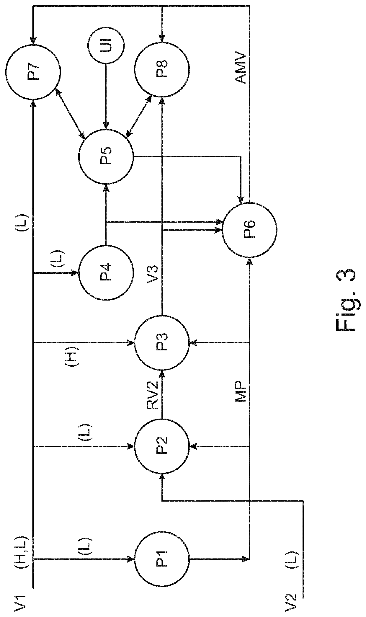
[0089]FIG. 3 shows a data flow diagram illustrating data transformation processes for producing a dual detail level combined presentation as described herein. A number of data processing functions P1 to P8 are illustrated, which will be detailed below and related to the previously described image processing system. FIG. 3 provides the methods described herein.

[0090]In the example of FIG. 3, a first volume of imaging data V1 is received corresponding to an arterial phase after contrast agent injection. A second volume of imaging data V2 is also received corresponding to a delayed phase after the arterial phase. The use of arterial and delayed phase imaging data is preferred, but not necessary as shown by the embodiment of FIG. 4 (described further below) which does not make use of dual phase imaging data. The imaging data is received through the data receiving module 100. The first volume of imaging data V1 can be received in two forms: at high detail (i.e. higher spatial resolution)...

second embodiment

[0100]FIG. 4 illustrates a data flow diagram for an alternative embodiment that does not make use of dual phase imaging data. FIG. 4 provides the methods described herein. In this case the registration process P2 and the volume enhancement process P4 of FIG. 3 can be omitted. Instead, a single volume of imaging data V1 can be obtained, which is sent to the low detail rendering process P7 at a low detail level for the imaging data and which is sent to the high detail rendering process P8 at a high detail level. Based on at least one virtual injection point obtained through presentation control process P5, an injection simulation is run through process P6 to produce an annotated mapping volume AMV designating at least one injected area that will be reached by an injection performed at the at least one virtual injection point to be rendered by the high detail rendering process P8. Further, graphical annotations will be included by the presentation control process P5 so as to mark in th...


PUM


Abstract

Visualization of a region of interest and planning a location of at least one injection point for a medical procedure is provided. At least one volume of imaging data for a region of interest is received. At least one virtual injection point is obtained. The at least one injection point indicates a location in a network of blood vessels for at least one injection. First and second rendering modules are controlled to construct a combined volume presentation including a first volume region rendered by a first rendering module at a relatively low level of detail and a second volume region is rendered at a higher level of detail by a second rendering module. The first and second volume regions are designated based on the at least one virtual injection point.

Description

FIELD OF THE INVENTION[0001]The technical field generally relates to visualization of a region of interest by way of a volume presentation and planning a location of an injection point. In particular, the volume presentation allows planning of an injection point for a transarterial catheter embolization procedure.BACKGROUND OF THE INVENTION[0002]A technique called transarterial catheter embolization (TACE) is used to deliver cancer treatment directly to a tumor through minimally-invasive means. A combination of chemotherapy drugs and embolization material is used to block off (embolize) the blood supply to the tumor.[0003]The TA(C)E procedure is typically performed in the “angio-suit”. By puncturing the common femora artery in the right groin or the radial artery in the wrist, a catheter is guided through the arterial system near the area to be treated.[0004]Here, a micro catheter is guided in the proper distal artery that supplies the tumor, where the agent is pushed into the tumor...

Claims


Application Information

Patent Timeline
Patent Type & Authority Applications(United States)
IPC IPC(8): A61B6/00A61B6/03A61B34/10G06T15/08
CPCA61B6/507A61B6/032A61B6/4085G06T15/08G06T2207/30096A61B6/504A61B2034/107A61B6/481G06T2207/30104A61B6/469A61B6/4441G06T2210/41G06T2207/30056G06T2210/36A61B34/10G06T2207/30101
Inventor MIELEKAMP, PIETER MARIAVAN DER STERREN, WILLIAM EDWARD PETER
Owner KONINKLJIJKE PHILIPS NV
Why Eureka
Try Eureka