Deposition processes for photovoltaics

a technology of photovoltaics and deposition processes, applied in the direction of sustainable manufacturing/processing, inks, final product manufacturing, etc., can solve the problems of limited light conversion efficiency, low yield of commercial processes, and limited ability to control product properties through process parameters

Inactive Publication Date: 2012-12-20
PRECURSOR ENERGETICS
View PDF27 Cites 23 Cited by
  • Summary
  • Abstract
  • Description
  • Claims
  • Application Information

AI Technical Summary

Benefits of technology

[0011]This invention relates to processes and compositions used to prepare semiconductor and optoelectronic materials and devices including thin film solar cells. In particular, this invention relates to deposition processes and compositions containing polymeric precursors for preparing CIGS and other solar cells.

Problems solved by technology

The difficulties with these approaches include lack of uniformity, purity and homogeneity of the CIGS layers, leading ultimately to limited light conversion efficiency.
Other disadvantages in the production of thin film devices are limited ability to control product properties through process parameters and low yields for commercial processes.
Absorber layers suffer from the appearance of different solid phases, as well as imperfections in crystalline particles and the quantity of voids, cracks, and other defects in the layers.
In general, CIGS materials are complex, having many possible solid phases.
Moreover, methods for large scale manufacturing of CIGS and related thin film solar cells can be difficult because of the chemical processes involved.
In general, large scale processes for solar cells are unpredictable because of the difficulty in controlling numerous chemical and physical parameters involved in forming an absorber layer of suitable quality on a substrate, as well as forming the other components of an efficient solar cell assembly, both reproducibly and in high yield.
In another example, introducing alkali ions at a controlled concentration into various layers and compositions of a CIGS-based solar cell has not been achieved in a general way.
Conventional methods for introducing sodium do not readily provide homogenous concentration levels or control over sodium location in a CIGS film.
A significant problem is the inability in general to precisely control the stoichiometric ratios of metal atoms and Group 13 atoms in the layers.
Without direct control over those stoichiometric ratios, processes to make semiconductor and optoelectronic materials can be less efficient and less successful in achieving desired compositions and properties.

Method used


Image

  • Deposition processes for photovoltaics
  • Deposition processes for photovoltaics
  • Deposition processes for photovoltaics

Examples


example 1

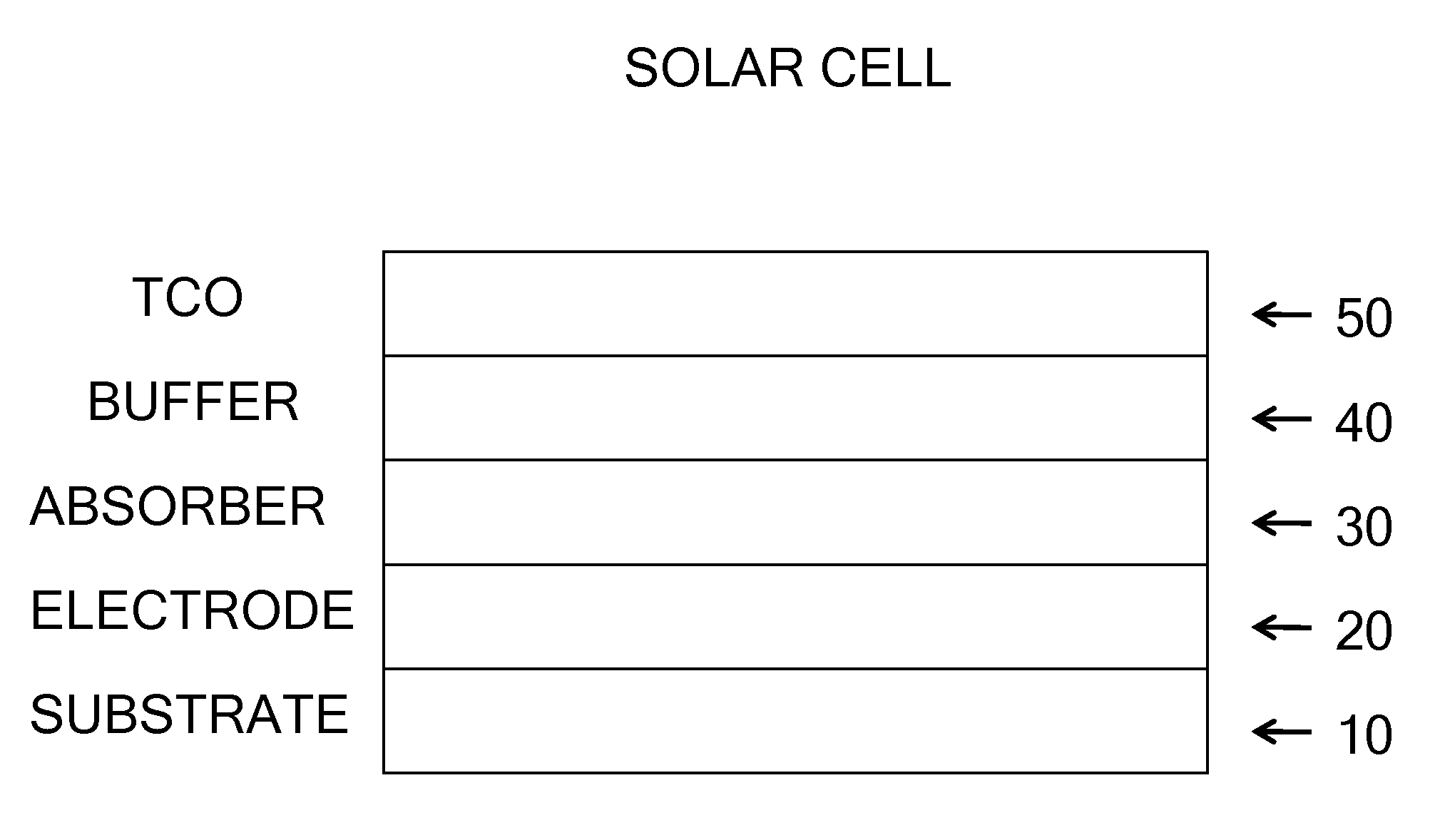
[0721]A CIGS absorber layer for a solar cell was made by the following process.

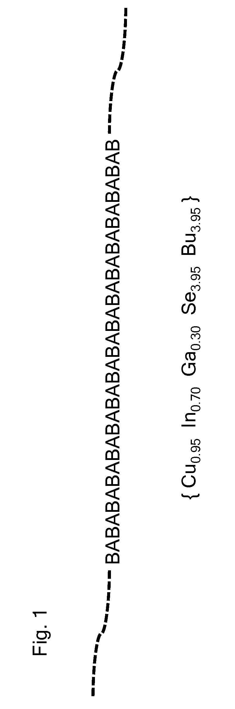
[0722]A first ink was prepared by dissolving the Cu-enriched CIGS polymeric precursor compound {Cu2.0In0.7Ga0.3(SetBu)2.0(SenBu)3.0} with 0.5 at % Na added supplied via NaIn(SenBu)4 in heptane, 50% polymeric precursor content, by weight, in an inert atmosphere glove box. The resulting ink was filtered through a 0.2 μm PTFE syringe filter prior to use.

[0723]A second ink was made by dissolving In(SesBu)3 and Ga(SesBu)3 in the ratio In to Ga of 70:30, in heptane, 50% content, by weight, in an inert atmosphere glove box. The resulting ink was filtered through a 0.2 μm PTFE syringe filter prior to use.

[0724]An 0.06 mL aliquot of the first ink was deposited onto a piece of 2 inch by 2 inch square Mo-coated sodalime glass substrate using a knife coater in an inert nitrogen atmosphere glove box with a knife speed of 10 mm / s. The wet substrate was transferred to a 90° C. hot plate for 1 minute to dry, then heated ...

example 2

[0727]A CIGS absorber layer for a solar cell was made by the following process.

[0728]A first ink was prepared by dissolving the Cu-enriched CIGS polymeric precursor compound {Cu2.0In0.7Ga0.3(SetBu)2.0(SenBu)3.0} with 0.5 at % Na added supplied via NaIn(SenBu)4 in heptane, 50% polymeric precursor content, by weight, in an inert atmosphere glove box. The resulting ink was filtered through a 0.2 μm PTFE syringe filter prior to use.

[0729]A second ink was made by dissolving In(SesBu)3 and Ga(SesBu)3 in the ratio In to Ga of 70:30, in heptane, 50% content, by weight, in an inert atmosphere glove box. The resulting ink was filtered through a 0.2 μm PTFE syringe filter prior to use.

[0730]An 0.08 mL aliquot of the first ink was deposited onto a piece of 2 inch by 2 inch square Mo-coated sodalime glass substrate using a knife coater in an inert nitrogen atmosphere glove box with a knife speed of 6 mm / s. The wet substrate was transferred to a 90° C. hot plate for 1 minute to dry, then heated a...

example 3

[0733]A CIGS absorber layer for a solar cell was made by the following process.

[0734]A first ink was made by dissolving In(SenBu)3 and In(SesBu)3 in the ratio 30:70, along with Ga(SenBu)3 and Ga(SesBu)3 in the ratio 30:70, so that the overall ratio of In to Ga was 70:30, in heptane, 50% content, by weight, in an inert atmosphere glove box. The resulting ink was filtered through a 0.2 μm PTFE syringe filter prior to use.

[0735]A second ink was prepared by dissolving the Cu-enriched CIGS polymeric precursor compound {Cu2.0In0.7Ga0.3(SetBu)2.0(SenBu)3.0} with 0.5 at % Na added supplied via NaIn(SenBu)4 in heptane, 50% polymeric precursor content, by weight, in an inert atmosphere glove box. The resulting ink was filtered through a 0.2 μm PTFE syringe filter prior to use.

[0736]A third ink was prepared by dissolving the Cu-enriched CIGS polymeric precursor compound {Cu2.0In0.7Ga0.3(SetBu)2.0(SenBu)3.0} with 0.5 at % Na added supplied via NaIn(SenBu)4 in heptane, 25% polymeric precursor co...


PUM

PropertyMeasurementUnit
temperatureaaaaaaaaaa
thicknessaaaaaaaaaa

Abstract

Processes for making a solar cell by depositing various layers of components on a substrate and converting the components into a thin film photovoltaic absorber material. Processes of this disclosure can be used to control the stoichiometry of metal atoms in making a solar cell, and for targeting a particular concentration. CIGS thin film solar cells can be made.

Description

CROSS REFERENCE TO RELATED APPLICATIONS[0001]This application claims the benefit of U.S. Provisional Application No. 61 / 498,383, filed Jun. 17, 2011, which is hereby incorporated by reference in its entirety.BACKGROUND[0002]One way to produce a solar cell product involves depositing a thin, light-absorbing, solid layer of the material copper indium gallium diselenide, known as “CIGS,” on a substrate. A solar cell having a thin film CIGS layer can provide low to moderate efficiency for conversion of sunlight to electricity.[0003]Making a CIGS semiconductor generally requires using several source compounds and / or elements which contain the atoms needed for CIGS. The source compounds and / or elements must be formed or deposited in a thin, uniform layer on a substrate. For example, deposition of the CIGS sources can be done as a co-deposition, or as a multistep deposition. The difficulties with these approaches include lack of uniformity, purity and homogeneity of the CIGS layers, leadin...

Claims


Application Information

Patent Timeline
Patent Type & Authority Applications(United States)
IPC IPC(8): H01L31/0264C09D11/00H01L31/18
CPCH01L31/0256C07F5/003Y02E10/541H01L31/0749C09D11/52H01L31/0322Y02P70/50
Inventor FUJDALA, KYLE L.ZHU, ZHONGLIANGJOHNSON, PAUL R. MARKOFFPADOWITZ, DAVIDCHOMITZ, WAYNE A.
Owner PRECURSOR ENERGETICS
Why Eureka
Try Eureka