Plunger lift slug controller

a technology of slug controller and slug body, which is applied in the direction of fluid removal, borehole/well accessories, construction, etc., can solve the problem of not being able to adjust for the case where the current liquid load is presen

Active Publication Date: 2012-12-20
LEA JR JAMES F
View PDF2 Cites 31 Cited by
  • Summary
  • Abstract
  • Description
  • Claims
  • Application Information

AI Technical Summary

Benefits of technology

[0012]Therefore, one object of the invention is to control the size of the liquid load during the shut in time so that plunger will rise and not stall out. The intra-cycle, i.e., “within the cycle”, method of the invention does not require assessing performance on a completed current cycle to make recommendations for a subsequent cycle. The current practice of making adjustments for subsequent cycles based

Problems solved by technology

The current practice of making adjustments for subsequent cycles based on information from completed current cycles results in a

Method used


Image

  • Plunger lift slug controller
  • Plunger lift slug controller
  • Plunger lift slug controller

Examples


Embodiment Construction

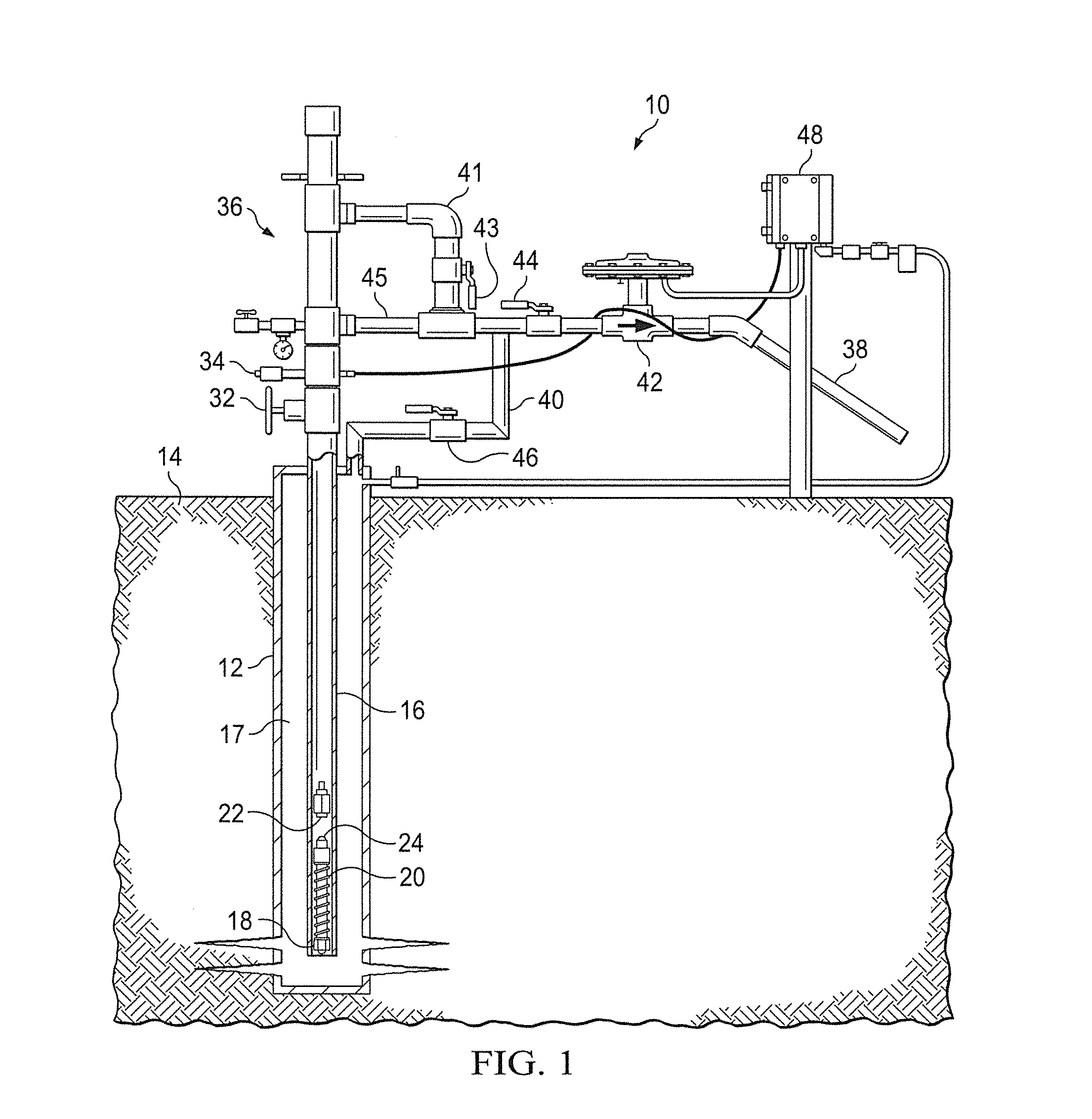
[0033]Referring to FIG. 1, shown is a plunger lift well 10 having casing 12 that extends below a ground surface 14. Tubing 16 extends into casing 12, defining annulus 17 therebetween. A tubing stop 18 is affixed at a lower end of tubing 16. A bumper spring 20 is supported by tubing stop 18 for engaging plunger 22 when plunger 22 falls during shut in of well 10.

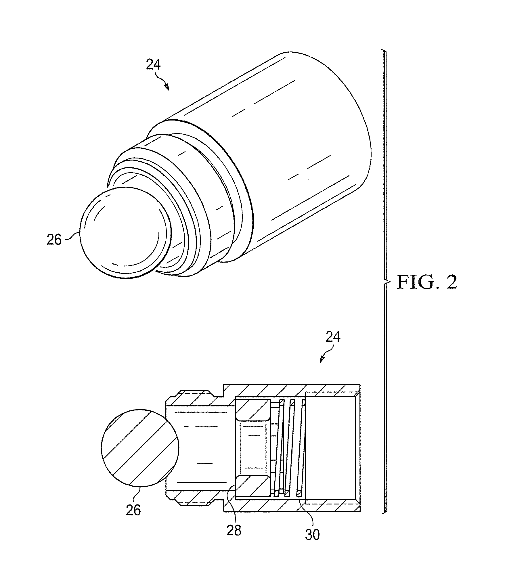
[0034]The bumper spring assembly 20 may include a spring loaded ball and seat assembly 24 (FIGS. 1, 2) made up of ball 26 received within seat 28. Relief spring 30 communicates with seat 28. Spring 30, having a correctly set spring compression, will prevent liquid in tubing 16 from falling out of tubing 16 during a shut in period of the plunger lift cycle. However, if the compression force of relief spring 30 is low enough, then equalizing pressure between casing 12 and tubing 16 for short intermittent times should still allow for compression of spring 30 and for some liquid to be pushed through seat 28. If the compression of ...


PUM


Abstract

A method for controlling the liquid load size of a plunger lift well during the shut in time of the well to facilitate a controlled plunger rise. Intra-cycle control allows dynamic adjustments within a cycle to keep the plunger running and not stalling out or rising too fast. The method includes the steps of shutting in the well to build up pressure within the well, adjusting a size of a liquid slug within the tubing while the well is shut in, opening a valve to relieve pressure within the well and raise the plunger within the tubing, pushing the liquid slug out of the well with the plunger, and closing the valve wherein the plunger falls within the tubing. The intra-cycle adjustments include reducing the size of the liquid slug for preventing fluid loading and increasing the size of the liquid slug for controlling a rise rate of the plunger.

Description

CROSS REFERENCE TO RELATED APPLICATIONS[0001]This application claims the priority of U.S. Provisional Patent Application No. 61 / 499,001, entitled “PLUNGER LIFT SLUG CONTROLLER,” filed Jun. 20, 2011, the contents of which are hereby incorporated by reference.BACKGROUND OF THE INVENTION[0002]Liquid loading of the wellbore is often a serious problem in aging production wells. Operators commonly use beam lift pumps or remedial techniques, such as venting or “blowing down” the well to atmospheric pressure to remove liquid buildup and restore well productivity. In the case of blowing down a well, the process must be repeated over time as fluids reaccumulate, resulting in additional methane emissions.[0003]Plunger lift systems are a cost-effective alternative to both beam lifts and well blowdowns and can make use of well energy to lift liquid from the well efficiently, i.e., to lift liquid with little or no slug fallback so that gas can flow without the obstruction of liquid loading for a ...

Claims


Application Information

Patent Timeline
IPC IPC(8): E21B43/16
CPCE21B47/0007E21B43/121E21B47/008E21B34/02
Inventor LEA, JR., JAMES F.
Owner LEA JR JAMES F
Why Eureka
Try Eureka