Fuel Injection Device

a fuel injection and fuel injection technology, applied in the direction of machines/engines, electrical control, applications, etc., can solve the problems of affecting the lift of the valve body at the intermediate lift position, causing accidents, unstable behavior of the valve body, etc., and achieves the effect of reducing the controllable amount of injection and low cos

Active Publication Date: 2012-12-20
HITACHI ASTEMO LTD
View PDF2 Cites 52 Cited by
  • Summary
  • Abstract
  • Description
  • Claims
  • Application Information

AI Technical Summary

Benefits of technology

[0010]According to the present invention, the fuel injection device that is low in the costs and reduces the controllable amount of injection is driven.

Problems solved by technology

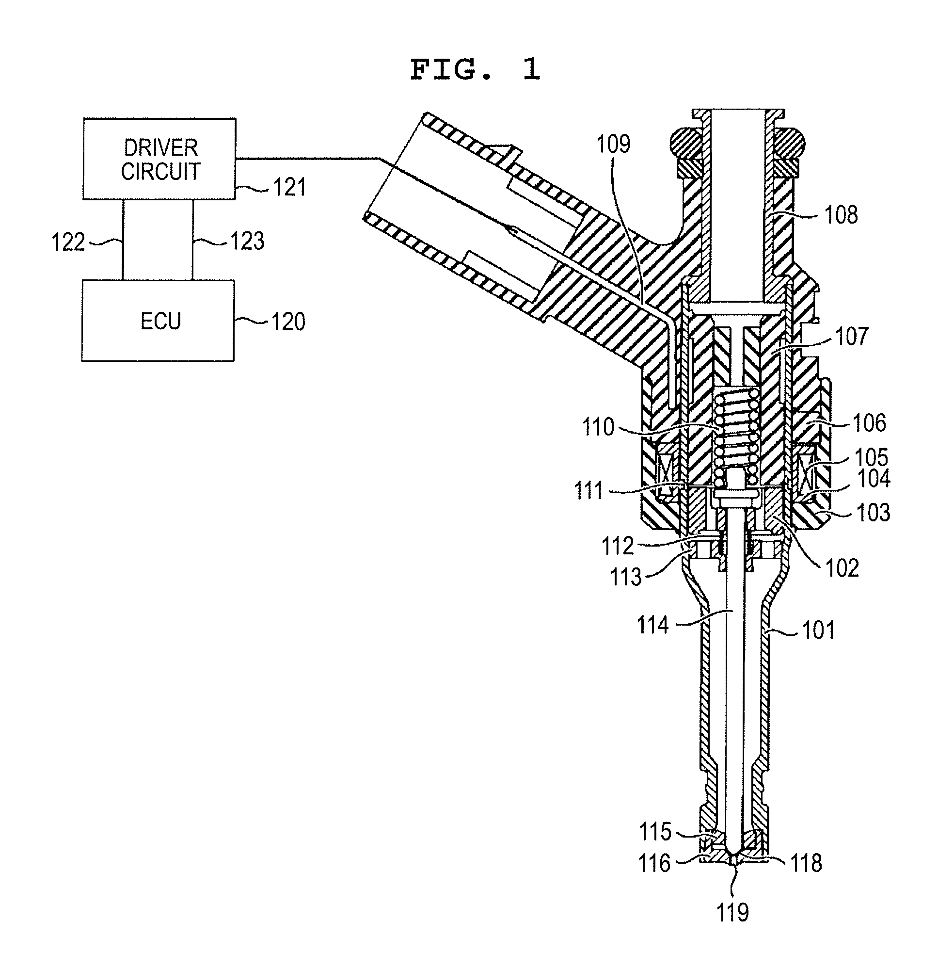
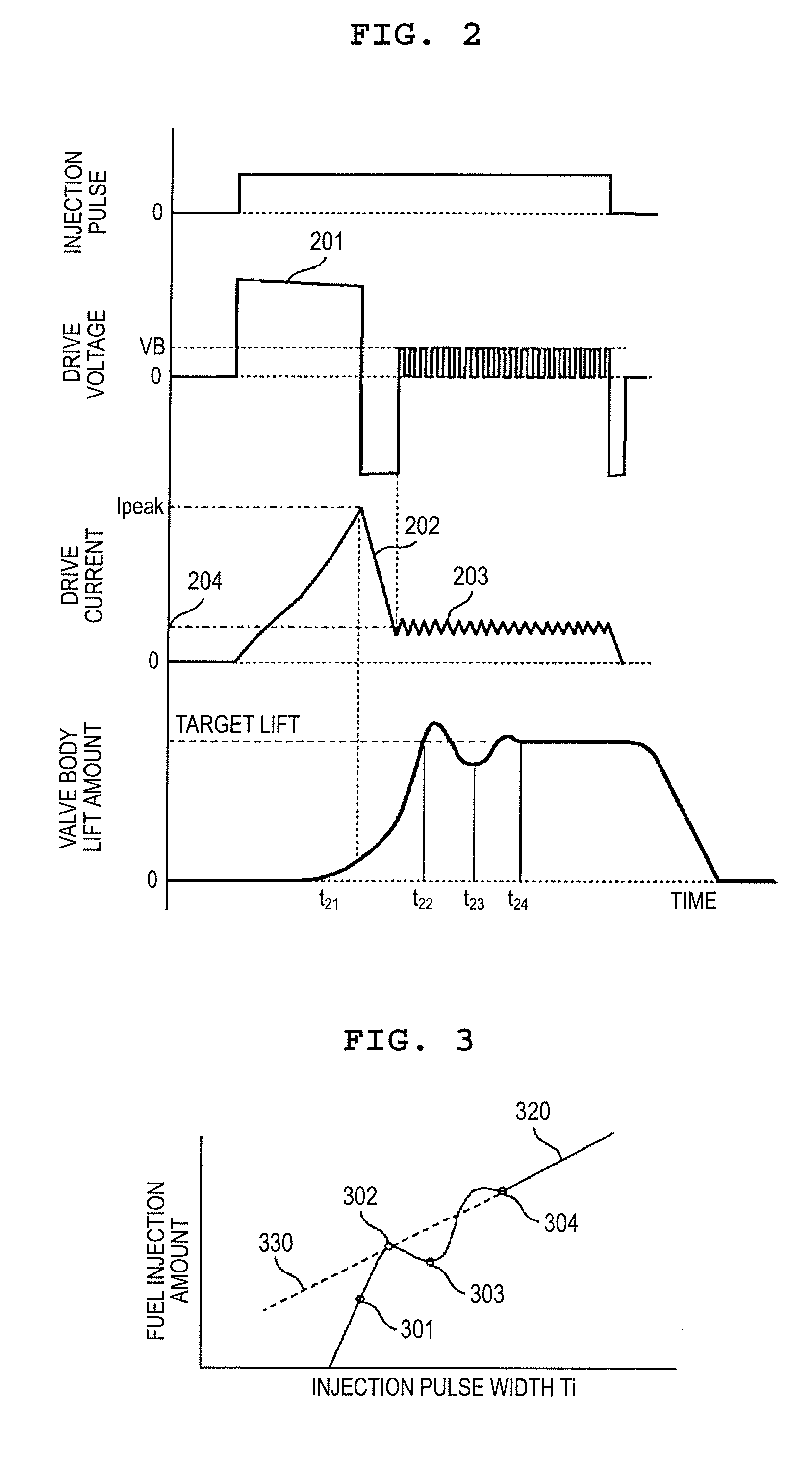
However, in an area where the driving pulse is short, a valve body does not arrive at a maximum lift position, and the valve body moves at a so-called “intermediate position” between a valve closed position and the full open position, and the behavior of the valve body is unstable.
The amount of lift of the valve body at the intermediate lift position is liable to be affected by a fluctuation in the fuel pressure.
This causes a possibility that an accident fire is induced.
In order that those methods are used for inexpensive electromagnetic values, a pressure sensor is required to control the amount of lift of the valve body, resulting in such a problem that it is difficult to use those methods for gasoline internal combustion engines from the viewpoint of the costs.
Also, the provision of the needle valve requires the pressure control chamber for controlling the needle valve, a regulating valve for adjusting a pressure within the pressure control chamber, and a driver for driving the regulating valve, resulting in such a problem that the configuration of the fuel injection device becomes complicated and large.

Method used


Image

  • Fuel Injection Device
  • Fuel Injection Device
  • Fuel Injection Device

Examples


first embodiment

[0030]Subsequently, a configuration and operation of a first embodiment according to the present invention will be described with reference to FIG. 4 and FIG. 5. FIG. 4 is a diagram illustrating a relationship of the amount of lift of the valve body 114, a force exerted on the valve body 114 in the valve closing direction, and a force exerted on the needle 102 in the valve opening direction. A solid line 410 in the figure represents an absolute value of the force exerted on the valve body 114 in the valve closing direction, and a broken line 411 represents an absolute value of the force exerted on the needle 102 in the valve opening direction.

[0031]In a state point 401 where no current is supplied to the solenoid 105, the valve body 114 is urged in the valve closing direction by the load of the spring 110 and a force caused by the fuel pressure (hereinafter referred to as “hydrodynamic force”). When a current is supplied to the solenoid 105, an attractive force, which is a force in ...

second embodiment

[0036]A second embodiment according to the present invention will be described with reference to FIG. 7. FIG. 7 is an enlarged cross-sectional view illustrating a valve body tip in a fuel injection device according to the second embodiment of the present invention. In FIG. 7, the same constituent components as those in FIGS. 1 and 5 are denoted by identical numerals or symbols.

[0037]In an example illustrated in FIG. 7, in the configuration of the first embodiment, a seat diameter ds1 of the valve body 114 is reduced, and a tapered surface 701 is provided upstream of the seat diameter ds1. The hydrodynamic force exerted on the valve body 114 when the valve is closed is a product of the area of the seat diameter ds1 and the fuel pressure. Therefore, the seat diameter ds1 is reduced so that the force exerted on the valve body 114 in the valve closing direction can be reduced when the valve is closed. Also, when a taper 701 is formed upstream of the seat diameter ds1, as compared with a...

third embodiment

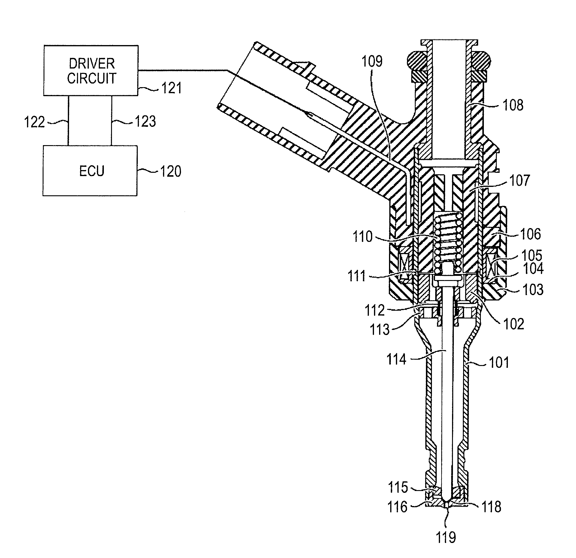
[0038]A third embodiment according to the present invention will be described with reference to FIGS. 1 and 8. FIG. 8 is an enlarged cross-sectional view illustrating a valve body tip in a fuel injection device according to the third embodiment of the present invention. Referring to FIG. 8, the same constituent components as those in FIGS. 1 and 5 are denoted by identical numerals or symbols.

[0039]In an example illustrated in FIG. 8, in the configuration of the first embodiment, a seat diameter ds2 of the valve body 114 is reduced, a taper 801 is provided upstream of the seat diameter ds2, and an inclined portion 803 is provided on an orifice cup 116. With the above configuration, a slight gap hg1 can be defined between the taper 801 and the inclined portion 803. In addition to the vicinity of the seat diameter ds1 of the valve body 114, the range where the static pressure is reduced by the Bernoulli's theorem can be provided in the taper 801. The same effects as those described abo...


PUM


Abstract

A method of controlling a fuel injection device that can control a small amount of injection is provided. A fuel injection device for use in an internal combustion engine, includes: a valve body that can open and close a fuel passage, a needle that transfers a force with the valve body, and executes valve opening / closing operation, and an electromagnet that includes a coil and a magnetic core provided as a driver for driving the needle, and a cylindrical nozzle holder disposed on an outer periphery of the magnetic core and the needle, in which a current is supplied to the coil to exert a magnetic attractive force between the magnetic core and the needle to open the valve body.

Description

BACKGROUND OF THE INVENTION[0001]1. Field of the Invention[0002]The present invention relates to a fuel injection device used for an internal combustion engine, a driving method and a driver circuit for the fuel injection.[0003]2. Background Art[0004]In recent years, from the viewpoints of the tougher control of carbon dioxide emission and concerns about exhaustion of fossil fuels, lower fuel consumption for an internal combustion engine has been demanded. For that reason, an effort to decrease the fuel consumption has been exerted by a reduction of various losses in the internal combustion engine. In general, when the losses are reduced, an output necessary for driving the engine is lowered with the result that the lowest output of the internal combustion engine is also lowered.[0005]In the above internal combustion engine, there is a need to control the amount of fuel to be small enough for the lowest output for feeding the fuel. In recent years, as a technique for decreasing the ...

Claims


Application Information

Patent Timeline
IPC IPC(8): F02M63/00
CPCF02D2041/2055F02D2041/2058F02D2200/0618F02D41/20F02M61/1833F02M51/0671F02M45/12F02M51/0685F02D2041/2013F02M63/0033F02M59/366F02M51/0653
Inventor KUSAKABE, RYOABE, MOTOYUKIYASUKAWA, YOSHIHITOMAEKAWA, NORIYUKIMAYUZUMI, TAKUYAISHIKAWA, TOHRU
Owner HITACHI ASTEMO LTD
Why Eureka
Try Eureka