Apparatus and Method For Gripping and Releasing Objects

Inactive Publication Date: 2012-12-20
ELLIS JOSEPH D +1
View PDF3 Cites 24 Cited by
  • Summary
  • Abstract
  • Description
  • Claims
  • Application Information

AI Technical Summary

Benefits of technology

[0013]As previously stated, the actuating system may be operated to close the breach in the substantially contiguous vacuum path, while suction is admitted into the airflow passageway in the body via the vacuum supply port. Thus, air entering the intake on the object gripper will be pulled through the intake, the object gripper, the body and the vacuum supply port, along the corridor provided by the substantially contiguous vacuum path, substantially without interruption or interference from air that did not enter the device through the intake. The volume and velocity of the suction applied at the vacuum supply port may be adjusted so as to produce about the area of the contact a pressure gradient force having a magnitude that is equal to or greater than, and opposite in direction to, the object's weight (i.e., the downward gravitational force exerted on the object by the earth's gravitational field), thereby counteracting the force of gravity and causing the object to be pinned against the intake on the object gripper. At this point, the object may be lifted, rotated or moved in space by lifting, rotating or moving the apparatus.
[0014]Operating the actuating system to open the breach permits air to pass into the device through the open breach and then directly into the airflow passageway in the body without first flowing through the object gripper. The additional volume of air passing into the airflow passageway from the open breach swiftly moves through the body to satisfy the negative air pressure forces created by the suction, effectively “short circuiting” the substantially contiguous vacuum path and substantially reducing or eliminating the flow of air through the intake on the ob

Problems solved by technology

In these and other industries, it is frequently necessary or desirable to grip, lift and/or move objects or materials without direct human contact with the objects because, for example, the objects need to be moved with speed, volume or precision that cannot be achieved or sustained by humans, because the objects are too heavy, inaccessible, hazardous or dangerous to humans, or because moving the objects by human labor is too expensive or unreliable.
There are a number of technical problems associated with using conventional devices and methods for picking up, moving and releasing objects.
First, conventional end-of-arm tooling devices, such as venturi suction devices with suction pads, are known to be unreliable and inefficient at holding, controlling and releasing certain types of objects during the high-speed accelerations and

Method used


Image

  • Apparatus and Method For Gripping and Releasing Objects
  • Apparatus and Method For Gripping and Releasing Objects
  • Apparatus and Method For Gripping and Releasing Objects

Examples


Embodiment Construction

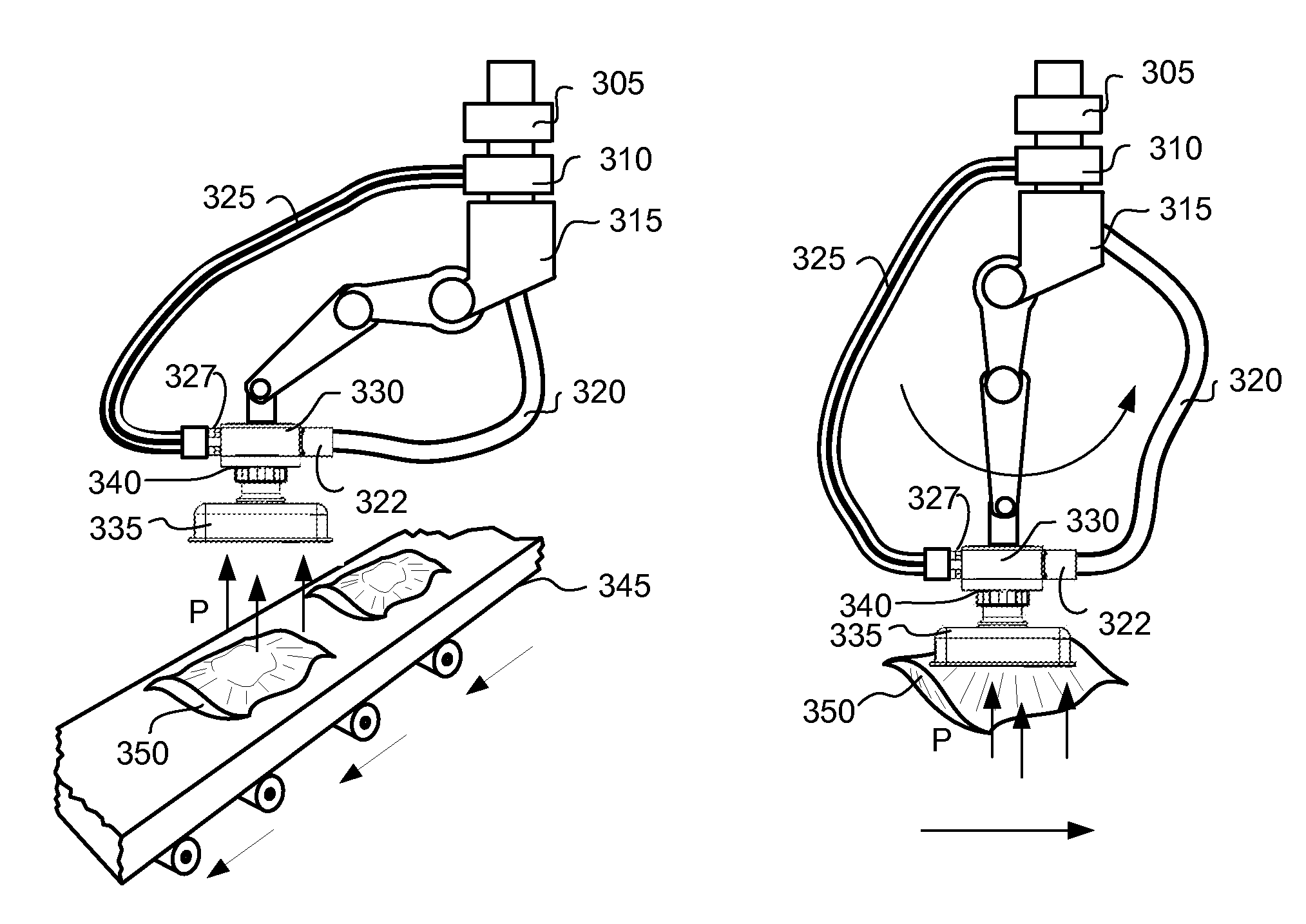
[0037]Non-limiting examples of devices and methods arranged and configured to grip and release objects and materials according to certain embodiments and variations of the present invention will now be described in some detail by reference to the figures.

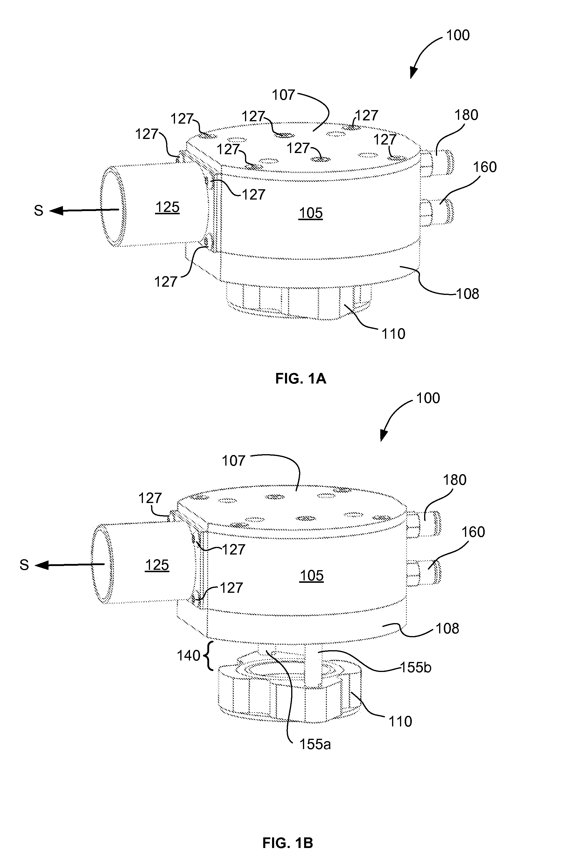
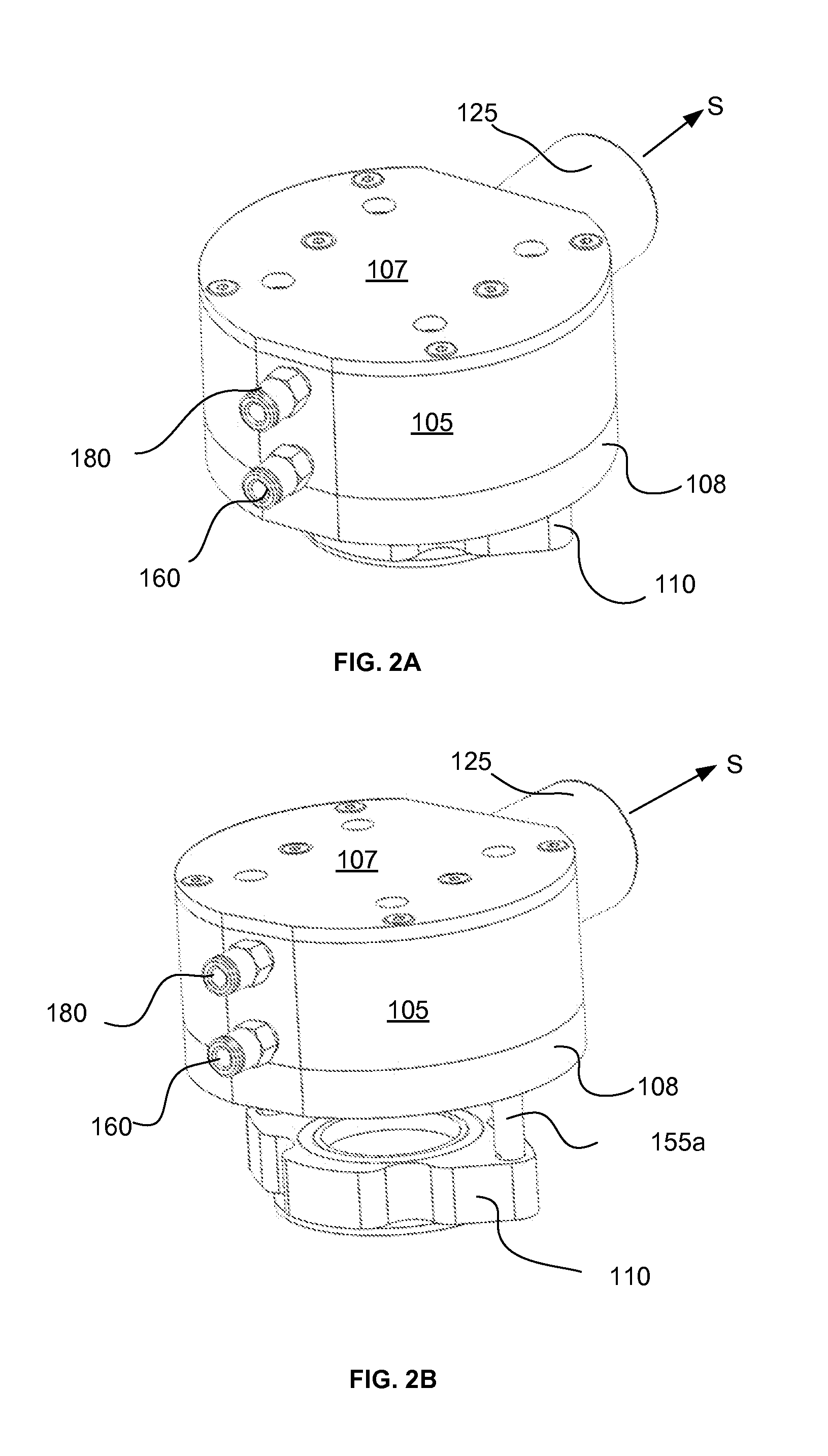
[0038]FIGS. 1A, 1B, 2A, 2B, 3A, 3B, 4A, 4B and 4C (referred to collectively as FIGS. 1A through 4C) show various views and positions of an exemplary end effector 100 arranged according to one embodiment of the present invention. Right perspective views (from above) of the exemplary end effector 100 are shown in FIGS. 1A and 1B, rear perspective views (from above) are shown in FIGS. 2A and 2B, and front perspective views (from below) are shown and FIGS. 3A and 3B. Left side, top side and bottom side orthogonal views of the exemplary end effector 100 are shown in FIGS. 4A, 4B and 4C, respectively.

[0039]As shown in FIGS. 1A through 4C, exemplary end effector 100 includes a body 105, an adapter flange 110, movably attached to the body 1...


PUM


Abstract

Improved devices and methods for gripping, supporting and releasing objects, which may be used with robotic arms, manipulators or vehicles, to hold, move or rotate objects in automated manufacturing, packaging, assembling and construction applications. The device comprises a body, an adapter flange for mounting an object gripper with an intake, a vacuum supply port, an airflow passageway configured to couple the intake to the vacuum supply port to define a substantially contiguous vacuum path, and an actuating system to open and close a breach in the substantially contiguous vacuum path. Admitting suction via the vacuum supply port while the breach is closed and the intake is in contact with the object produces a pressure gradient force having sufficient magnitude to support the object's weight in a gravitational field. Operating the actuating system to open the breach releases the object and preferably propels it away from the device.

Description

TECHNICAL FIELD[0001]Certain embodiments of the present invention pertain generally to devices and methods for gripping and releasing objects. Some embodiments and variations, but not all embodiments and variations, pertain more specifically to end-of-arm tools, end effectors and heads for machines and vehicles, such as robotic arms, manipulators and cranes, and methods for using same to grip, lift and release objects.RELATED ART[0002]Technology relevant to embodiments and variations of the present invention may be found in a wide variety of industries, including, for example, manufacturing, packaging, materials handling, food processing, assembly, construction, shipping, transportation, science, medicine and pharmaceuticals. In these and other industries, it is frequently necessary or desirable to grip, lift and / or move objects or materials without direct human contact with the objects because, for example, the objects need to be moved with speed, volume or precision that cannot be...

Claims


Application Information

Patent Timeline
IPC IPC(8): B25J15/06
CPCB25J15/0616
Inventor ELLIS, JOSEPH D.MCENTIRE, MICHAEL
Owner ELLIS JOSEPH D
Why Eureka
Try Eureka