
Efficient halogen lamp

a halogen lamp, efficient technology, applied in the field of lamps, can solve problems such as deformation of filament supports, and achieve the effect of preventing high current arcing and high melting poin

Inactive Publication Date: 2012-12-20
GENERAL ELECTRIC CO
View PDF2 Cites 8 Cited by
  • Summary
  • Abstract
  • Description
  • Claims
  • Application Information

AI Technical Summary

Benefits of technology

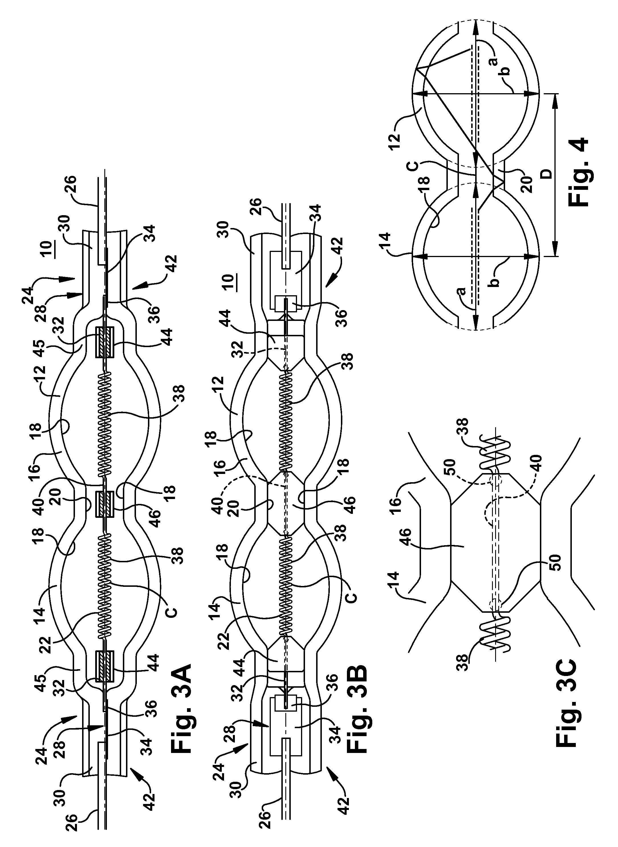
[0005]Referring to specific aspects of the lamp described above, each of the elliptical portions has a major axis and a minor axis, wherein the major axis can be between about 12 mm and 17 mm and the minor axis (mm) can be approximately equal to 1.2*(major axis−5). The central portion of the envelope can be in a shape of a cylindrical tube. The filament support can be made of metal having a high melting point (e.g., above 1800-2000° C.), for example, tungsten or molybdenum. The filament can be designed for a line voltage of 230-240 volts and the lamp can be operated at 25-150 W. An infrared radiation reflecting coating can be disposed on a surface of the envelope. The lamp can be a halogen lamp in which case the gas comprises an inert gas containing halogen. For example, the gas may contain Ar, Kr, Xe, or N2, or combinations thereof as inert gases, and Cl, I, Br or F, or combinations thereof as halogens.
[0006]The filament can include single coil interval portions near the end portions of the envelope. The filament support can comprise side filament supports located near each of the ...

Problems solved by technology

On the other hand, the inner surface of the pinch portion is curved, which could cause deformation of the filament support during manufacturing.

Method used


Image

  • Efficient halogen lamp
  • Efficient halogen lamp
  • Efficient halogen lamp

Examples


Embodiment Construction

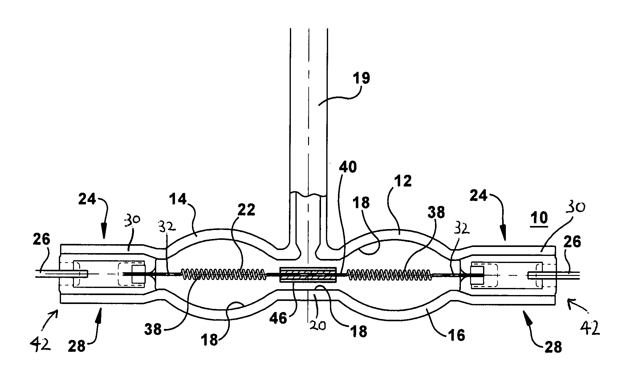
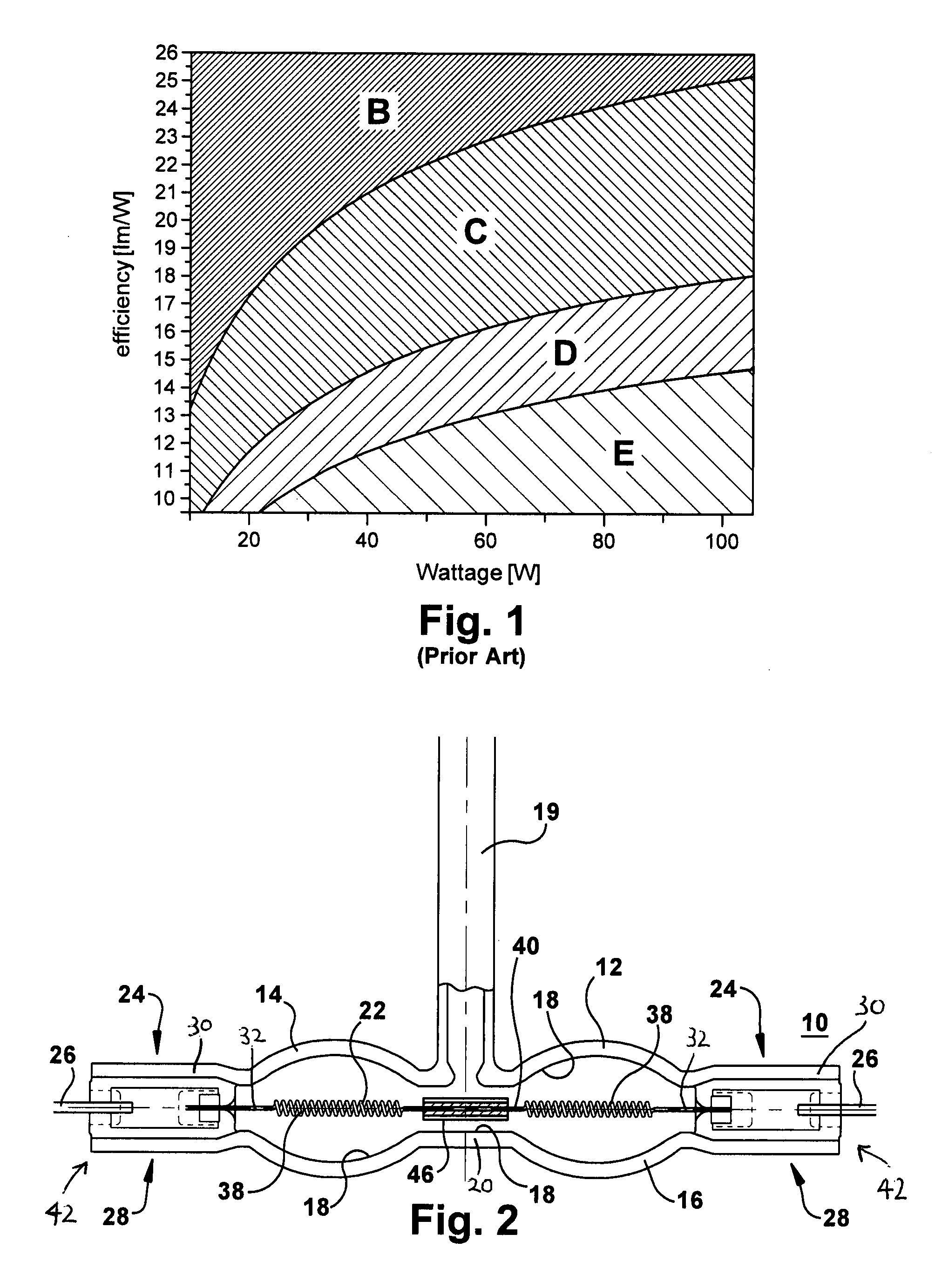
[0019]Referring to FIGS. 2 and 3, a lamp 10 of this disclosure includes a heat resistant, light transmissive bulb or envelope 12 having two connected elliptical portions 14, 16 forming a hollow interior 18. The envelope 12 is made of fused or synthetic silica (quartz). The lamp 10 of this disclosure ideally has two elliptical portions 14, 16 in particular, not one, and not three or more. The lamp disclosed here can be used in A-shaped bulbs, spherical shaped bulbs or candle shaped bulbs, for example. The two elliptical bulb portions can be connected with a central cylindrical tubular portion 20, all of which have an IR radiation reflecting coating on their outer surfaces (not shown). The central connecting bulb portion 20 is not distorted with, for example dunching. A fill gas tube 19 is shown centrally located in FIG. 2, but can instead be located between one of the elliptical portions and a pinch portion of the lamp shown in FIG. 3 in which case a longer side filament support 44 a...


PUM


Abstract

A lamp includes a light transmissive envelope comprising two spaced apart elliptical portions that together form a hollow interior. The envelope has sealed end portions. Leads are in electrical contact with the filament near the end portions of the envelope for providing power to the lamp. There is a central portion of the envelope that spaces apart the elliptical portions. An electrically conductive filament is disposed in the interior of the envelope. The filament includes coiled-coil portions disposed in the elliptical portions in a coiled-coil shape and a single coil interval portion disposed between the coiled-coil portions at the central portion of the envelope. At least one filament support positions the filament near a center of the envelope. Gas is contained in the interior of the envelope.

Description

FIELD OF THE INVENTION[0001]The field of the invention is lamps, in particular, halogen lamps, that have high efficiency. This high efficiency can be brought about by the shape of the envelope of the lamp and the configuration and position of the filament in the lamp.BACKGROUND OF THE INVENTION[0002]As shown in FIG. 1, in Europe 230-240V line voltage halogen lamps today are in the lower range of the C class range close to the D class range boundary. However, B class efficiency is the most desirable. The application of an infrared reflecting coating to the lamp can improve lamp efficiency, so to reach the B energy class is theoretically possible.[0003]There are several major requirements of the halogen lamp design with infrared (IR) reflecting technology developed to produce higher efficiency halogen lamps. IR reflectivity and visible transmission of the infrared reflecting multilayer should be increased. Bulb and filament shape should be optimized to reflect infrared radiation back ...

Claims


Application Information

Patent Timeline
IPC IPC(8): H01K1/28H01K1/08H01K1/14H01K1/50
CPCH01K1/24H01K5/02H01K3/06H01K1/28
Inventor CSEH, GEZA ZOLTANFAZEKAS, FERENCNAGY, PETER LAJOSBALLA, LASZLOMEZEI, BELA
Owner GENERAL ELECTRIC CO
Learn More