Image display device and image display method

a technology of image display and display method, applied in the field of image display devices, can solve the problems of reducing display quality, increasing power consumption, and affecting the perception of peak brightness, and achieve the effects of simplified configuration, high speed, and simplified configuration

Inactive Publication Date: 2012-12-20
SHARP KK
View PDF4 Cites 14 Cited by
  • Summary
  • Abstract
  • Description
  • Claims
  • Application Information

AI Technical Summary

Benefits of technology

[0049]According to the ninth aspect of the present invention, besides the reverse gamma correction by the display reverse gamma correction section, the reverse gamma correction by the emission luminance reverse gamma correction section is performed, and in addition to this, another correction is separately performed to increase the values within the predetermined range of the emission luminance data, so that computation can be performed properly in accordance with the content of one correction separately from another.
[0050]According to the tenth aspect of the present invention, the emission luminance reverse gamma correction section references the first table (indicating a correspondence between input and output tones), and further, the luminance correction section references the second table, so that computation for each of the corrections can be performed at high speed with a simplified configuration.
[0051]According to the eleventh aspect of the present invention, the luminance correction section simultaneously (collectively) subjects the input image to the reverse gamma correction and the correction for increasing the values within the predetermined range of the emission luminance data, eliminating the need for the emission luminance calculation section to perform separate reverse gamma corrections, so that the amount of computation therefor, the circuit scale for such computation, etc., can be reduced.
[0052]According to the twelfth aspect of the present invention, the luminance correction section references a single table (indicating a correspondence between input and output tones), so that computation for a correction can be performed at high speed with a simplified configuration.
[0053]According to the thirteenth aspect of the present invention, the same effect as the effect achieved by the first aspect of the invention can be achieved by an area-active image display device.
[0054]According to the fourteenth aspect of the present invention, the same effect as the effect achieved by the first aspect of the invention can be achieved by the image display device control method.

Problems solved by technology

However, in the conventional device, when the mean image luminance is low, a low backlight luminance results in a reduction in display quality, e.g., peak brightness of pixels to be displayed with high tones being perceived somewhat low, or when the backlight luminance is insufficient (for a display luminance), a tone jump (insufficient luminance) or suchlike might occur at pixels to be displayed with high tones.
However, such a constantly high backlight luminance increases power consumption, and the entirely bright screen causes the peak brightness to be perceived somewhat low.

Method used


Image

  • Image display device and image display method
  • Image display device and image display method
  • Image display device and image display method

Examples


first embodiment

1. First Embodiment

[0068]

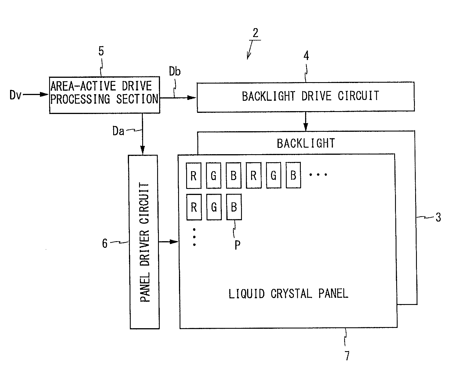
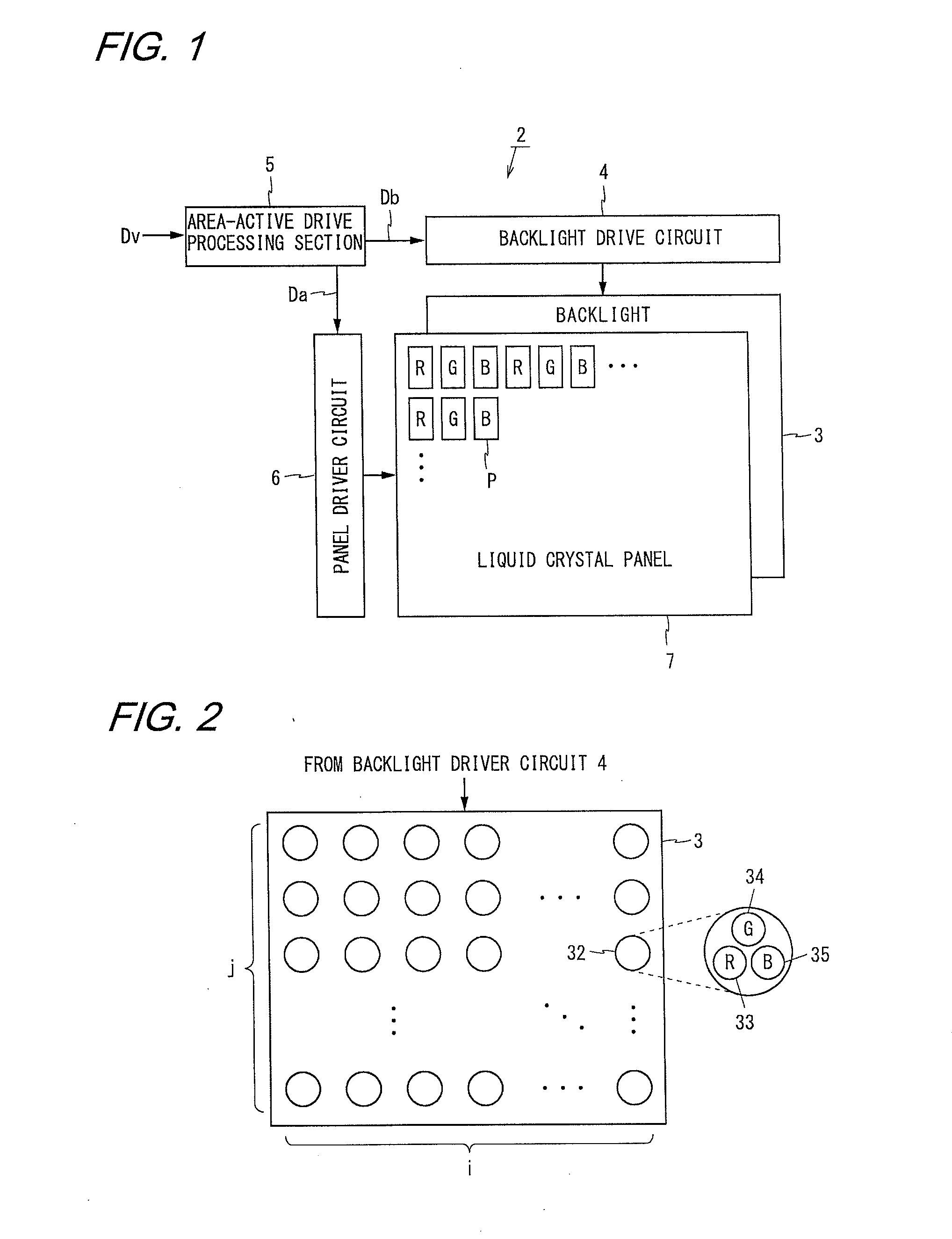
[0069]FIG. 1 is a block diagram illustrating the configuration of a liquid crystal display device 2 according to a first embodiment of the present invention. The liquid crystal display device 2 shown in FIG. 1 includes a backlight 3, a backlight driver circuit 4, a panel driver circuit 6, a liquid crystal panel 7, and an area-active drive processing section 5. The liquid crystal display device 2 performs area-active drive in which the liquid crystal panel 7 is driven with luminances of backlight sources being controlled on the basis of input image portions within a plurality of areas defined by dividing the screen. In the following, m and n are integers of 2 or more, i and j are integers of 1 or more, but at least one of i and j is an integer of 2 or more.

[0070]The liquid crystal display device 2 receives a signal which indicates an input image Dv including an R image, a G image, and a B image (hereinafter, the signal will also be simply referred to as the i...

second embodiment

2. Second Embodiment

[0114]

[0115]The configuration and the operation of a liquid crystal display device 2 according to a second embodiment of the present invention are almost the same as those of the liquid crystal display device 2 according to the first embodiment, except that the luminance correction LUT 13 in the present embodiment has different characteristics from the luminance correction LUT 13 in the first embodiment shown in FIG. 4.

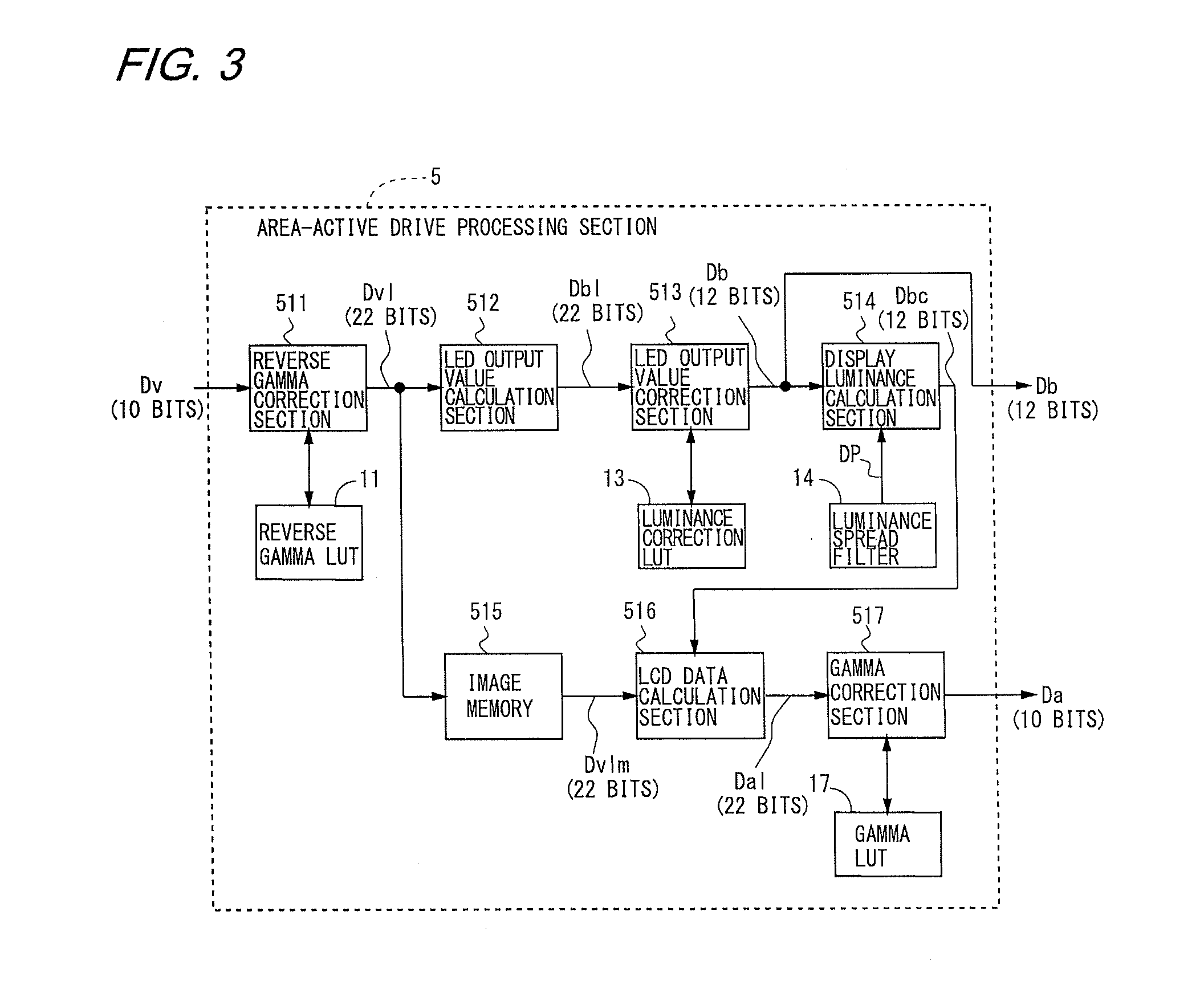
[0116]Specifically, the liquid crystal display device 2 according to the second embodiment of the present invention is configured in the same manner as the liquid crystal display device 2 according to the first embodiment shown in FIG. 1, the backlight 3 is also configured in the same manner as in the first embodiment shown in FIG. 2, the configuration of the area-active drive processing section 5 is also the same in detail as in the first embodiment shown in FIG. 3, except for the contents of the luminance correction LUT 13, and the processing pro...

third embodiment

3. Third Embodiment

[0127]

[0128]The configuration and the operation of a liquid crystal display device 2 according to a third embodiment of the present invention are almost the same as those of the liquid crystal display device 2 according to the first or second embodiment, except that the luminance correction LUT 13 in the present embodiment has different characteristics from the luminance correction LUT 13 in the first or second embodiment shown in FIG. 4 or 8.

[0129]Specifically, the liquid crystal display device 2 according to the third embodiment of the present invention, including the backlight 3, is configured in the same manner as the liquid crystal display device 2 according to the first or second embodiment, the configuration of the area-active drive processing section 5 is also the same in detail as in the first embodiment shown in FIG. 3, except for the contents of the luminance correction LUT 13, and the processing procedures are also the same as in the first embodiment s...


PUM


Abstract

In the present liquid crystal display device, an LED output value correction section (513) included in an area-active drive processing section (5) corrects LED data Dbl obtained by an LED output value calculation section (512) with reference to a luminance correction LUT (13), such that the luminance in the area from an intermediate value to near a maximum value shifts to a higher degree. Thus, even if the backlight luminance is low (typically, the mean luminance of an input image is low), contrast ratio is enhanced, thereby preventing a tone jump (insufficient luminance) at high tone levels due to an insufficient backlight luminance.

Description

REFERENCE TO RELATED APPLICATIONS[0001]This application is a national stage application under 35 USC 371 of International Application No. PCT / JP2010 / 070442, filed Nov. 17, 2010, which claims the priority of Japanese Patent Application No. 2010-055395, filed Mar. 12, 2010, the entire contents of which are incorporated herein by reference.FIELD OF THE INVENTION[0002]The present invention relates to image display devices, particularly to an image display device with the function of controlling the luminance of a backlight (backlight dimming function).BACKGROUND OF THE INVENTION[0003]Image display devices provided with backlights, such as liquid crystal display devices, can control the luminances of the backlights on the basis of input images, thereby suppressing power consumption by the backlights and improving the quality of display images. In particular, by dividing a screen into a plurality of areas and controlling the luminances of backlight sources corresponding to the areas on th...

Claims


Application Information

Patent Timeline
Patent Type & Authority Applications(United States)
IPC IPC(8): G09G5/10G09G3/36
CPCG09G3/3426G09G3/3611G09G2320/0276G09G2320/0626G09G3/3413G09G2320/066G09G2330/021G09G2360/16G09G2360/18G09G2320/0646G02F1/133G09G3/36
Inventor UENO, TETSUYAFUJIWARA, KOHJI
Owner SHARP KK
Why Eureka
Try Eureka