Bearing mounting arrangement for a drive train of a motor vehicle

Inactive Publication Date: 2012-12-20
DAIMLER AG
View PDF18 Cites 0 Cited by
  • Summary
  • Abstract
  • Description
  • Claims
  • Application Information

AI Technical Summary

Benefits of technology

[0009]The bracing device of the mounting arrangement according to the invention thus does not require control of any actuating elements which consume energy. The mounting device according to the invention exhibits not only less complexity, a low number of parts and associated low costs but also a low weight, which is favorable to the energy consumption of the motor vehicle for operation thereof. Furthermore the probability of breakdown of the mounting device according to the invention is extremely low due to the low complexity thereof.
[0011]This torque-dependent bearing tensioning reduces the power losses of the bearing, in particular in low and average torque ranges, whereby this results in a further reduction of the energy requirement for the operation of the motor vehicle. If for example a drive unit of the motor vehicle is an internal combustion engine this results in fuel reduction and a reduction of CO2 emissions. In comparison with known mounting devices a reduction of bearing losses by up to 30% is thus possible, which improves the degree of efficiency of the bearing operation.
[0012]Besides the fact that no additional sensors and / or control units are necessary, the mounting device according to the invention has the advantage that it only has a low construction space requirement and also requires only a minimum change of already existing components and can thus be integrated into already existing components and designs virtually without time-consuming and costly modification work. Furthermore subsequent fitting of already existing systems is possible with the mounting arrangement according to the invention.
[0015]Such a bearing tensioning brings about an optimal use of the bearing load capacity in all operating states, an avoidance of bearing play and tilting of the shaft and also a compensation capability for heat expansions.
[0016]The necessary and desirable bearing tension, that is the amount of the force acting in axial direction of the shaft, is normally experimentally determined and usually exactly set by means of spacing washers. The amount of the bearing tension needs to be based on the highest possible load effective on the shaft. This results in an additional bearing load and increases the torque-dependent bearing power losses over the whole spectrum of use. The use of an actuating element, for example in the form of an actuator, for targeted torque-dependent bearing pretension reduces the pretension in the partial load region and improves the degree of efficiency, but has the disadvantages already described.
[0018]The control part is advantageously arranged at an end face of the drive part facing the bearing ring and the actuating part is advantageously arranged on an end face of the bearing ring facing the drive part. This provides for a targeted and direct force transfer and a low construction space requirement of the mounting device according to the invention.

Problems solved by technology

This results in a relative rotation, that is a slight twisting, of the drive shaft part with respect to the bearing ring of the shaft depending on the amount of the torque applied.

Method used


Image

  • Bearing mounting arrangement for a drive train of a motor vehicle
  • Bearing mounting arrangement for a drive train of a motor vehicle
  • Bearing mounting arrangement for a drive train of a motor vehicle

Examples


Embodiment Construction

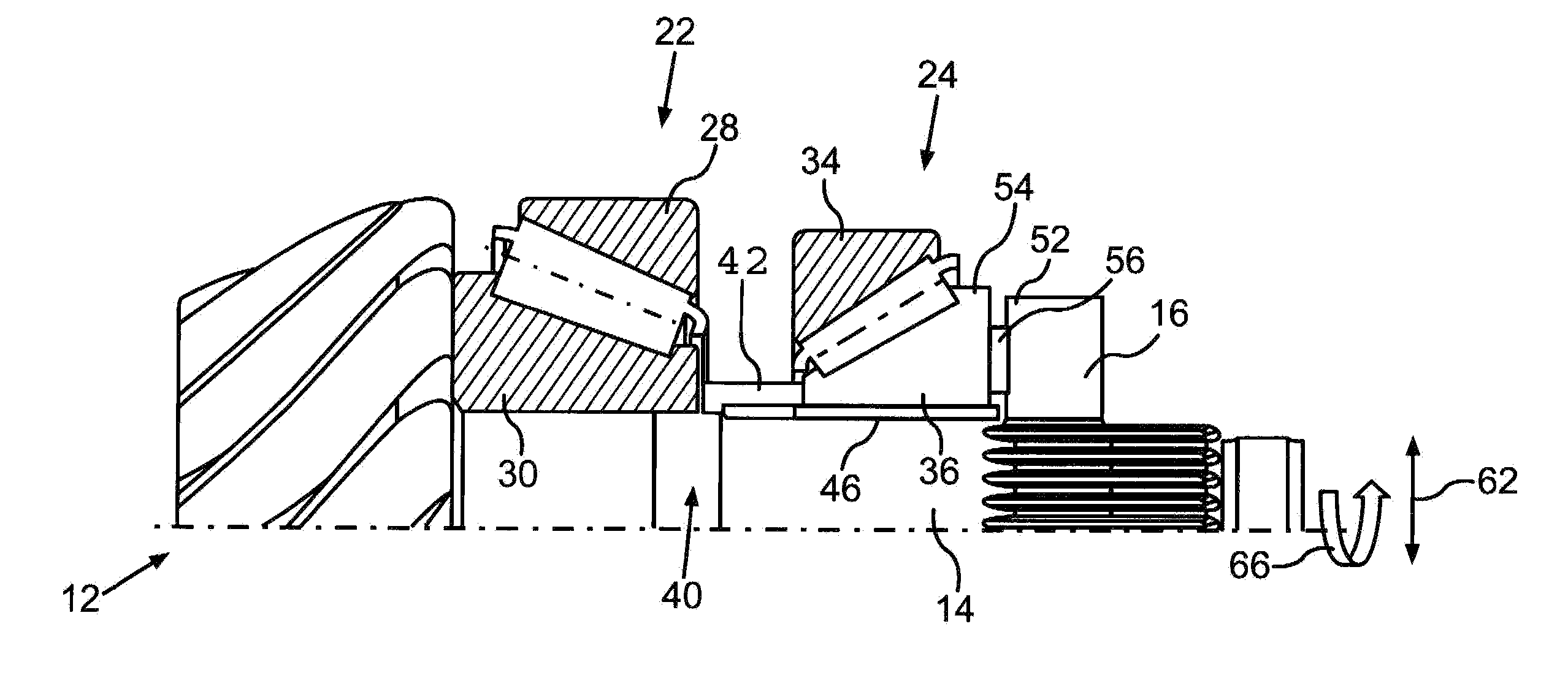
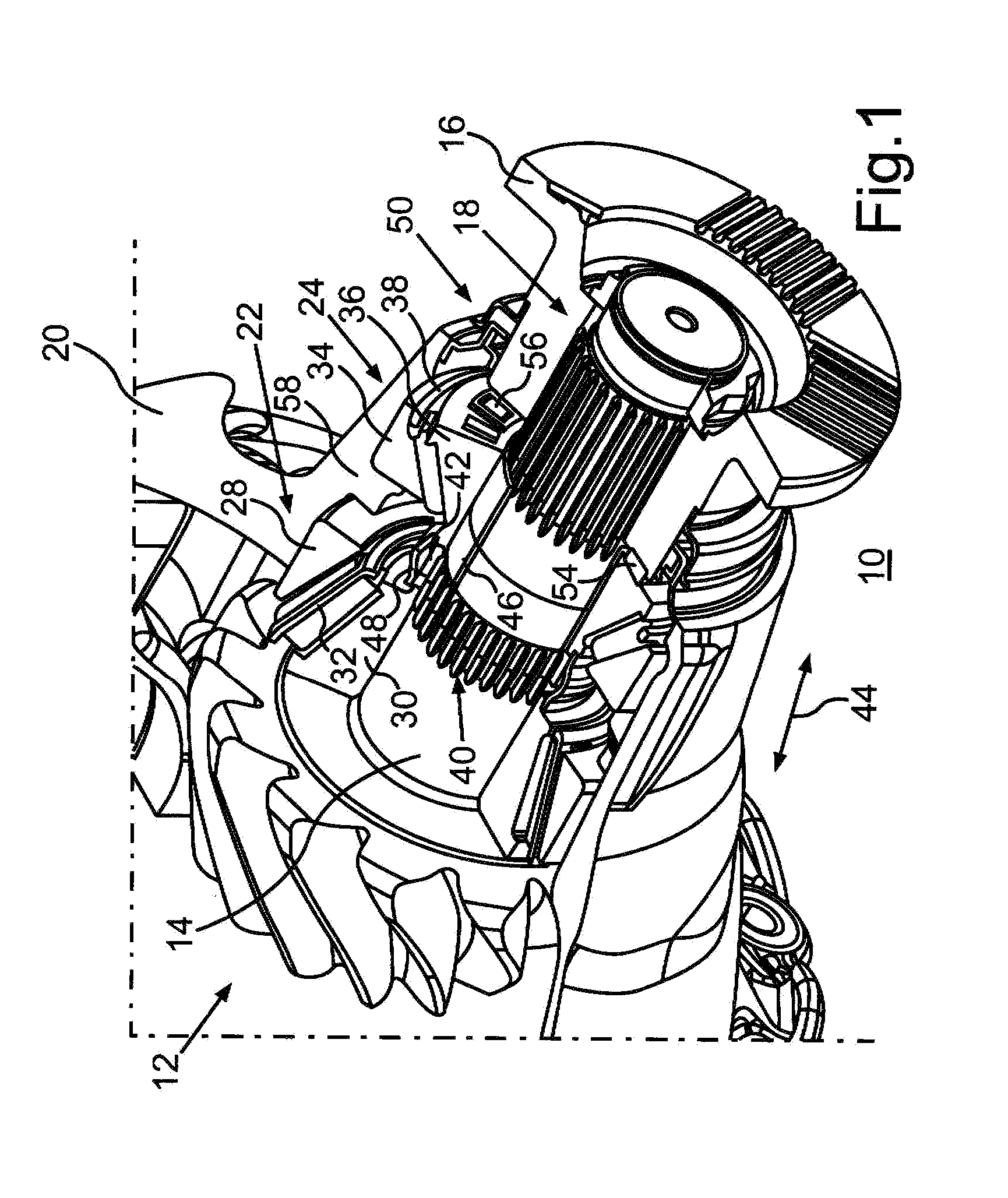
[0023]FIG. 1 shows a bearing mounting arrangement 10 for a drive train of a utility vehicle with a shaft 14 comprising a drive pinion 12 which is non-rotatably connected to a drive stub in the form of a coupling flange 16. The non-rotatable connection of the shaft 14 to the coupling flange 16 is established via toothing 18, via which during driving of the utility vehicle a torque can be transmitted by an internal combustion engine from the coupling flange 16 to the shaft 14 which then, in turn, drives a rear axle differential gear via its drive pinion 12.

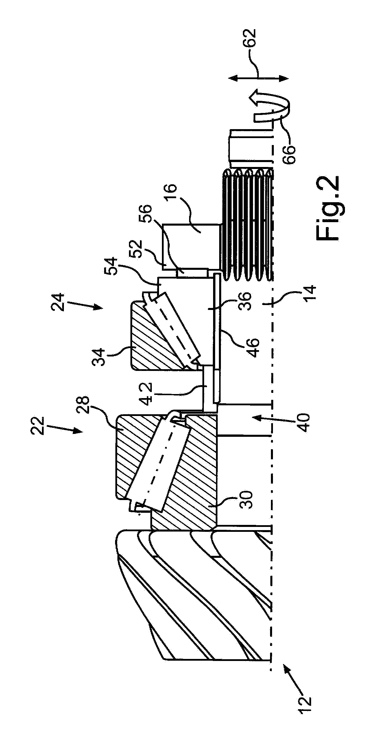
[0024]The shaft 14 is mounted in a housing 20 shown partially cut-out, via a first conical roller bearing 22 and via a second conical roller bearing 24, whereby the conical roller bearings 22 and 24 are arranged in an X-arrangement. The coupling flange 16 and the conical roller bearings 22 and 24 are accommodated partially within a mounting structure 10.

[0025]The conical roller bearing 22 comprises a bearing outer ring 28 which is f...


PUM


Abstract

In a bearing mounting arrangement for a drive train of a motor vehicle including a shaft having a drive part non-rotatably connected to the shaft and at least an outer bearing ring and an inner bearing ring which can be biased by means of a bracing device in axial direction of the shaft toward the outer bearing ring due to a relative rotation of the drive part with respect to the bearing ring with a bearing tensioning force which depends on a torque transmitted by the shaft so that the bearing tensioning force is relatively low during low-torque operation of the drive train.

Description

[0001]This is a Continuation-In-Part application of pending international patent application PCT / EP2010 / 005637 filed Sep. 14, 2010 and claiming the priority of German patent application 10 2009 058 560.5 filed Dec. 17, 2009.BACKGROUND OF THE INVENTION[0002]The invention relates to a bearing mounting arrangement for a drive train of a motor vehicle, including a drive component connected to a shaft and a bearing ring with an arrangement for applying an axial force to the bearing ring.[0003]DE 10 2005 027 082 A1 discloses a mounting device for motor vehicles, with two roller bearings, having outer bearing rings of which are arranged in a housing and inner bearing rings arranged on a shaft, and a tensioning device for axially bracing the outer rings with respect to the inner rings. The tensioning device thereby comprises an intermediate element which facilitates a change in the axial pretensioning of the roller bearings through a load-dependent change of its thickness dimensions. The in...

Claims


Application Information

Patent Timeline
IPC IPC(8): F16C23/00F16H57/021
CPCF16C19/54F16C25/08F16C35/063F16C19/56F16C2361/61F16C19/364F16C19/548F16H57/021
Inventor CLAUS, MATTHIASAZIZ, MOHD AZWAN
Owner DAIMLER AG
Why Eureka
Try Eureka