Impact wrench with improved redirection switch

a technology of impact wrench and redirection switch, which is applied in the direction of percussion drilling, percussive tools, manufacturing tools, etc., can solve the problems of reducing the output torque of the impact wrench and inconvenient operation for users, and achieves the effect of smooth operation and convenient operation

Inactive Publication Date: 2012-12-27
STORM PNEUMATIC TOOL CO LTD
View PDF8 Cites 15 Cited by
  • Summary
  • Abstract
  • Description
  • Claims
  • Application Information

AI Technical Summary

Benefits of technology

[0008]One objective of the invention is to provide an impact wrench with an

Problems solved by technology

Nevertheless, the above-mentioned redirection structure has the following problems.
Therefore, when a user holds the handle, it becomes

Method used


Image

  • Impact wrench with improved redirection switch
  • Impact wrench with improved redirection switch
  • Impact wrench with improved redirection switch

Examples


Embodiment Construction

[0023]The present invention will be apparent from the following detailed description, which proceeds with reference to the accompanying drawings, wherein the same references relate to the same elements.

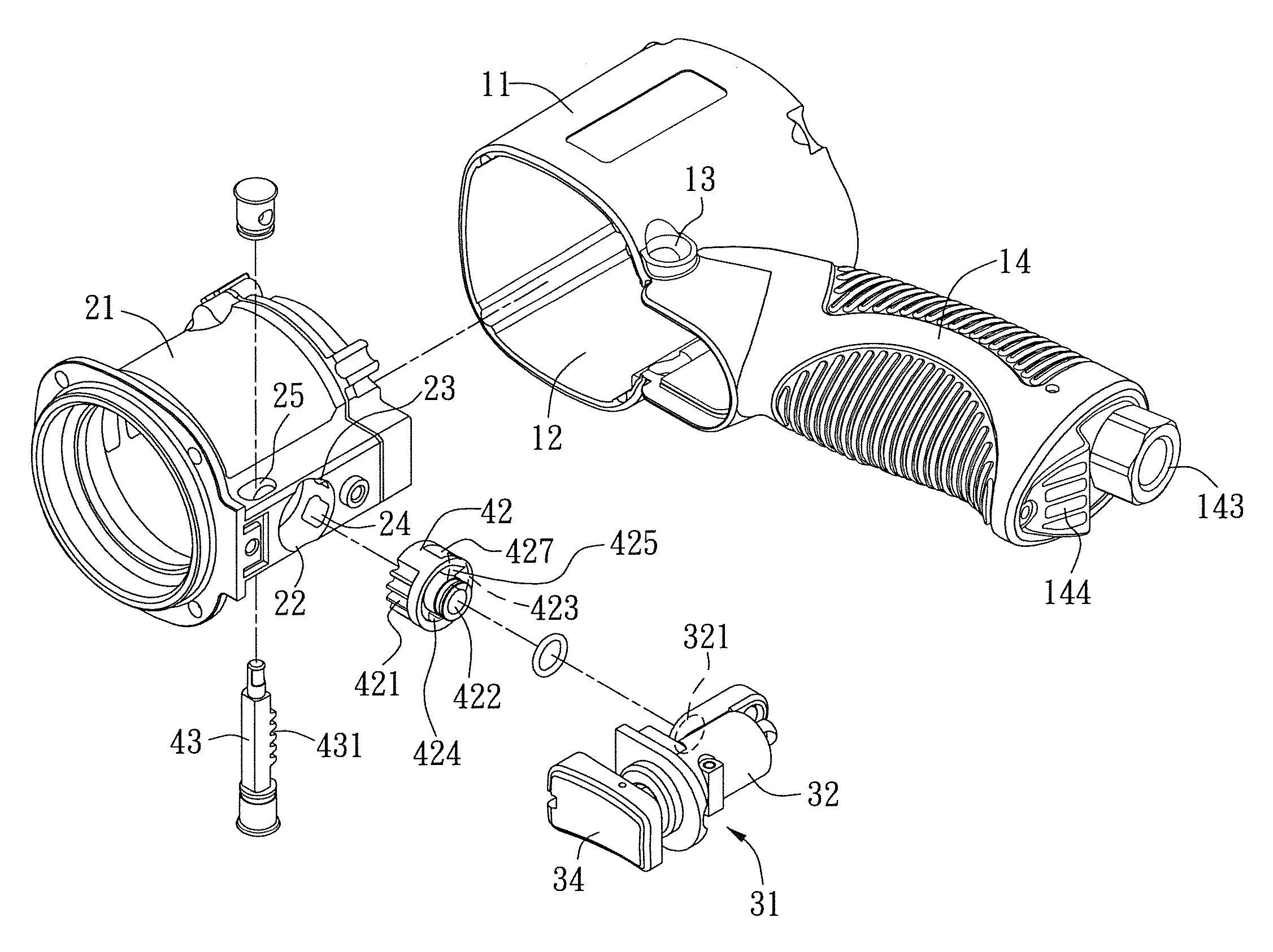
[0024]Please refer to FIGS. 1 to 5. The invention mainly consists of a housing 11, a motor shell 21, an on / off bar set 31, and a redirection switch 41.

[0025]The interior of the housing 11 has an accommodating space 12 and a through hole 13 penetrating through two opposite sides of the housing 11. The housing 11 has a handle 14 with an air intake passage 141 and an air exhaust passage 142. The air intake passage 141 has a connecting part 143 exposed from the bottom part of the handle 14 for connecting to a high-pressure air pipeline. The air exhaust passage 142 has several exhaust holes 144 at the bottom of the handle 14.

[0026]The motor shell 21 is disposed in the accommodating space 12 of the housing 11. The motor shell 21 is installed with a motor (not shown). The bottom part of the ...


PUM


Abstract

An impact wrench with an improved redirection switch includes a housing, a motor shell, an on/off bar set, and a redirection switch. The pushing bar of the redirection switch and the redirection valve are connected in tandem along the same horizontal line. The rotational axis of the rotating redirection valve is perpendicular to the penetrating axis of the on/off bar set, instead of the same penetrating axis line. Therefore, the invention achieves the redirection effect without increasing the volume of its handle.

Description

BACKGROUND OF THE INVENTION[0001]1. Field of Invention[0002]The invention relates to the structure of an impact wrench and, in particular, to an impact wrench with an improved redirection switch.[0003]2. Related Art[0004]The redirection structure of a conventional impact wrench is shown in FIGS. 8 and 9. The top part of its handle 7 is penetrated with a control bar 71. An air intake valve 72 is pivotally mounted on the control bar 71 and accommodated in an air valve sleeve 73. The air valve sleeve 73 has a forward hole 731 and a reverse air hole 732. The air intake valve 72 has a forward air intake hole 721 and a reverse air intake hole 722 corresponding to the forward and reverse holes 731, 732 of the air valve sleeve 73. The air intake valve 72 is driven by a switching bar 74 to rotate with respect to the air valve sleeve 73. When the air intake valve 72 rotates to a position so that the forward air intake hole 721 thereof and the forward hole 731 of the air valve sleeve 73 are co...

Claims


Application Information

Patent Timeline
IPC IPC(8): B25D11/00
CPCB25B21/02
Inventor SUN, YUNG-YUNGCHENG, CHUAN-CHING
Owner STORM PNEUMATIC TOOL CO LTD
Why Eureka
Try Eureka