

Sensor device
a sensor and sensor technology, applied in the field of sensor devices, can solve the problems of reducing the success rate of planer (plane) patch clamp system, reducing the success rate of specimen adsorption, and unable to easily carry out suction or adsorption, so as to achieve the effect of suppressing interference between specimens, improving measurement success rate, and easy suction and adsorption
- Summary
- Abstract
- Description
- Claims
- Application Information
AI Technical Summary
Benefits of technology
Problems solved by technology
Method used
Image

Examples
first exemplary embodiment
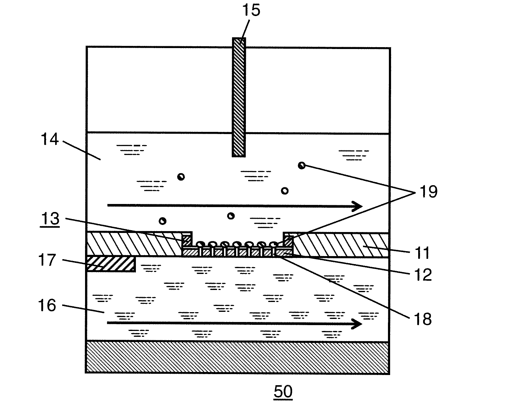
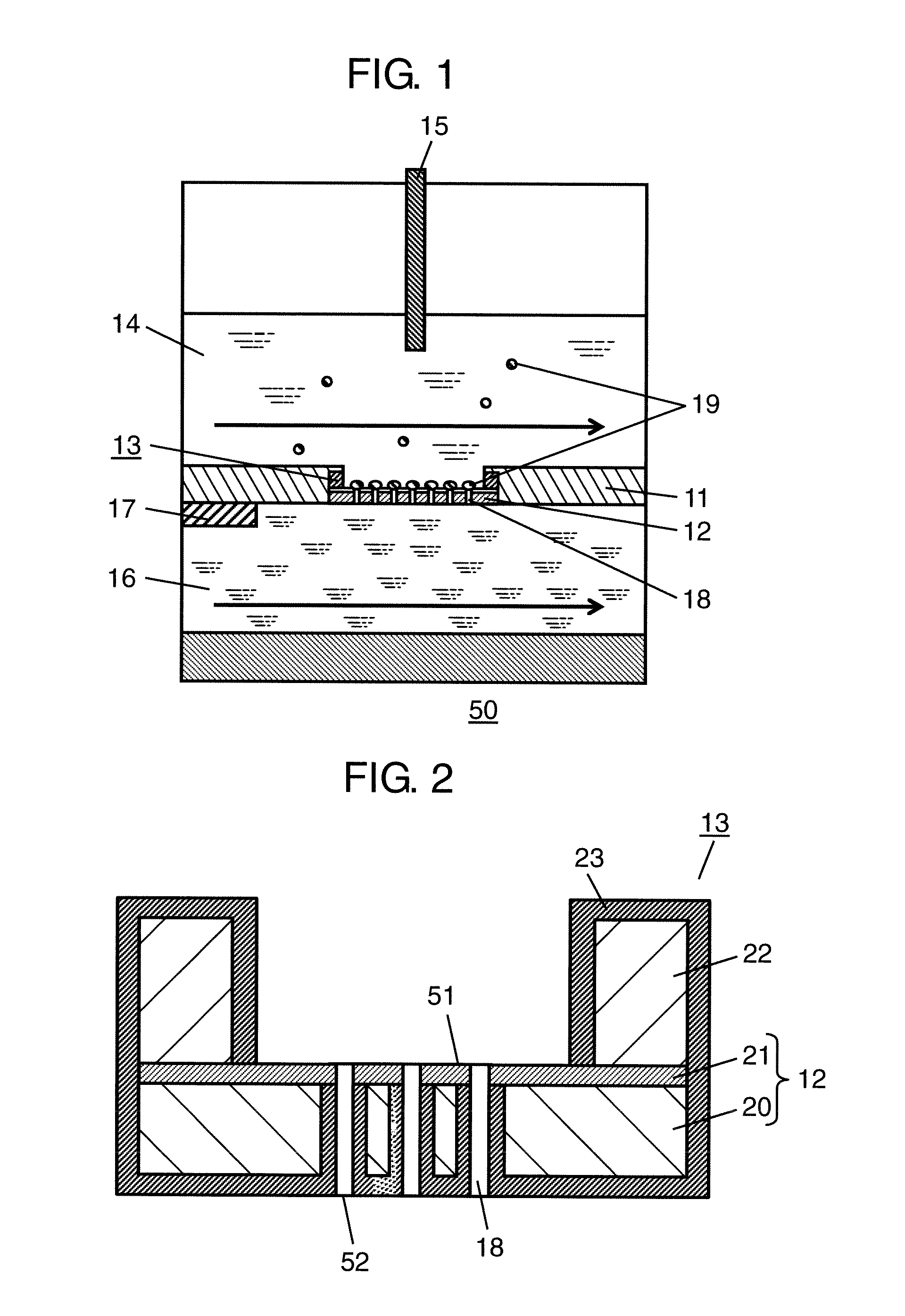
[0043]FIG. 1 is a schematic sectional view showing a configuration of cell electrophysiological sensor 50 as an example of a sensor device in accordance with a first exemplary embodiment of the present disclosure.
[0044]As shown in FIG. 1, cell electrophysiological sensor 50 in this exemplary embodiment includes substrate 11, and sensor chip 13 which is mounted on substrate 11 and has plate 12. Cell electrophysiological sensor 50 further includes first electrode bath 14 disposed above sensor chip 13 and first electrode 15 disposed inside of first electrode bath 14 and at an upper surface (first surface 51) side of sensor chip 13.
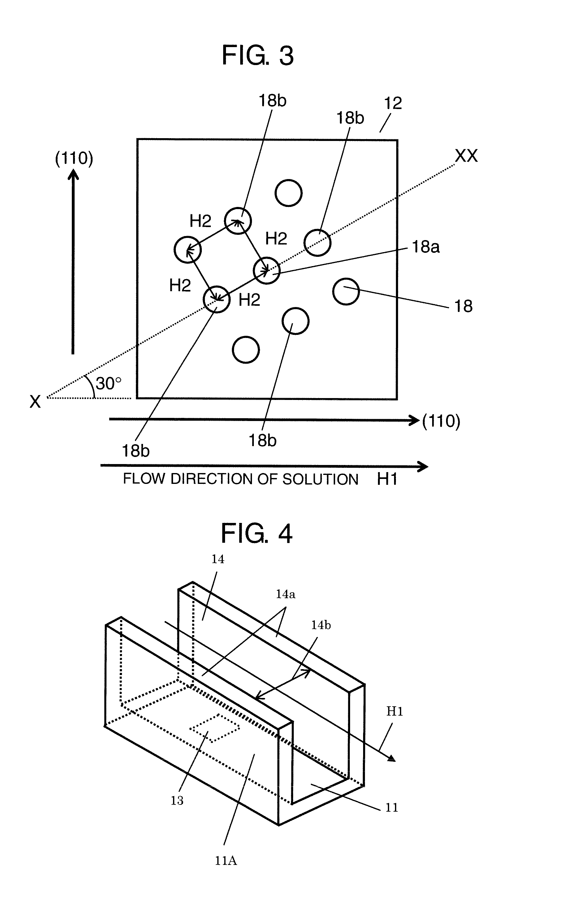
[0045]As shown in FIG. 4, flow channel 11A is disposed on substrate 11, and sensor chip 13 is disposed in flow channel 11A.
[0046]Furthermore, cell electrophysiological sensor 50 includes second electrode bath 16 disposed below sensor chip 13, and second electrode 17 disposed on the lower surface (second surface 52) of sensor chip 13 opposite side to the first...
second exemplary embodiment
[0158]Next, a second exemplary embodiment of the present disclosure is described.
[0159]Note here that the same reference numerals are given to the same components described in the first exemplary embodiment and the description thereof is omitted.
[0160]FIG. 12 is a sectional view showing a configuration of sensor chip 33 in accordance with the second exemplary embodiment of the present disclosure.
[0161]Sensor chip 33 of this exemplary embodiment is different from sensor chip 13 of the first exemplary embodiment in that an opening of through hole 38 does not have a circular shape but has a shape having a plurality of hole diameters, and in that the length direction of a longer hole diameter than the shortest length of the hole diameter of through hole 38 is parallel to solution flow direction H1.
[0162]As shown in FIG. 12, sensor chip 33 includes plate 32 having first surface 61 (upper surface) and second surface 62 (lower surface), and plate 32 is provided with a plurality of through ...
third exemplary embodiment
[0216]Hereinafter, a sensor device in accordance with a third exemplary embodiment of the present disclosure is described.
[0217]FIG. 20 is a schematic sectional view showing a configuration of a sensor device in accordance with the third exemplary embodiment of the present disclosure.
[0218]The same reference numerals are given to the same components described in the first and second exemplary embodiments and the description thereof is omitted. The first and second exemplary embodiments describe cell electrophysiological sensor 50 as an example of the sensor device, but the sensor device of the present disclosure can be also used as substance identification sensor 60. A sensor device in the substance identification sensor is a device capable of adsorbing and holding specimen 36 including a bead including a probe, and the like, and measuring a sample such as a chemical substance, a biological substance, and an environment substance.
[0219]As shown in FIG. 20, substance identification s...
PUM
| Property | Measurement | Unit |
|---|---|---|
| Length | aaaaa | aaaaa |
| Diameter | aaaaa | aaaaa |
| Shape | aaaaa | aaaaa |
Abstract
Description
Claims
Application Information