Slat monitoring system

Active Publication Date: 2012-12-27
AIRBUS OPERATIONS LTD
View PDF18 Cites 34 Cited by
  • Summary
  • Abstract
  • Description
  • Claims
  • Application Information

AI Technical Summary

Benefits of technology

[0017]Preferably, the inner and outer discs include sealing elements to prevent ingress of contaminants into said space between said discs.

Problems solved by technology

However, it will be appreciated that small differences in the detected and predetermined relative rates of rotation are acceptable and may not trigger an alarm signal.

Method used


Image

  • Slat monitoring system
  • Slat monitoring system
  • Slat monitoring system

Examples


Embodiment Construction

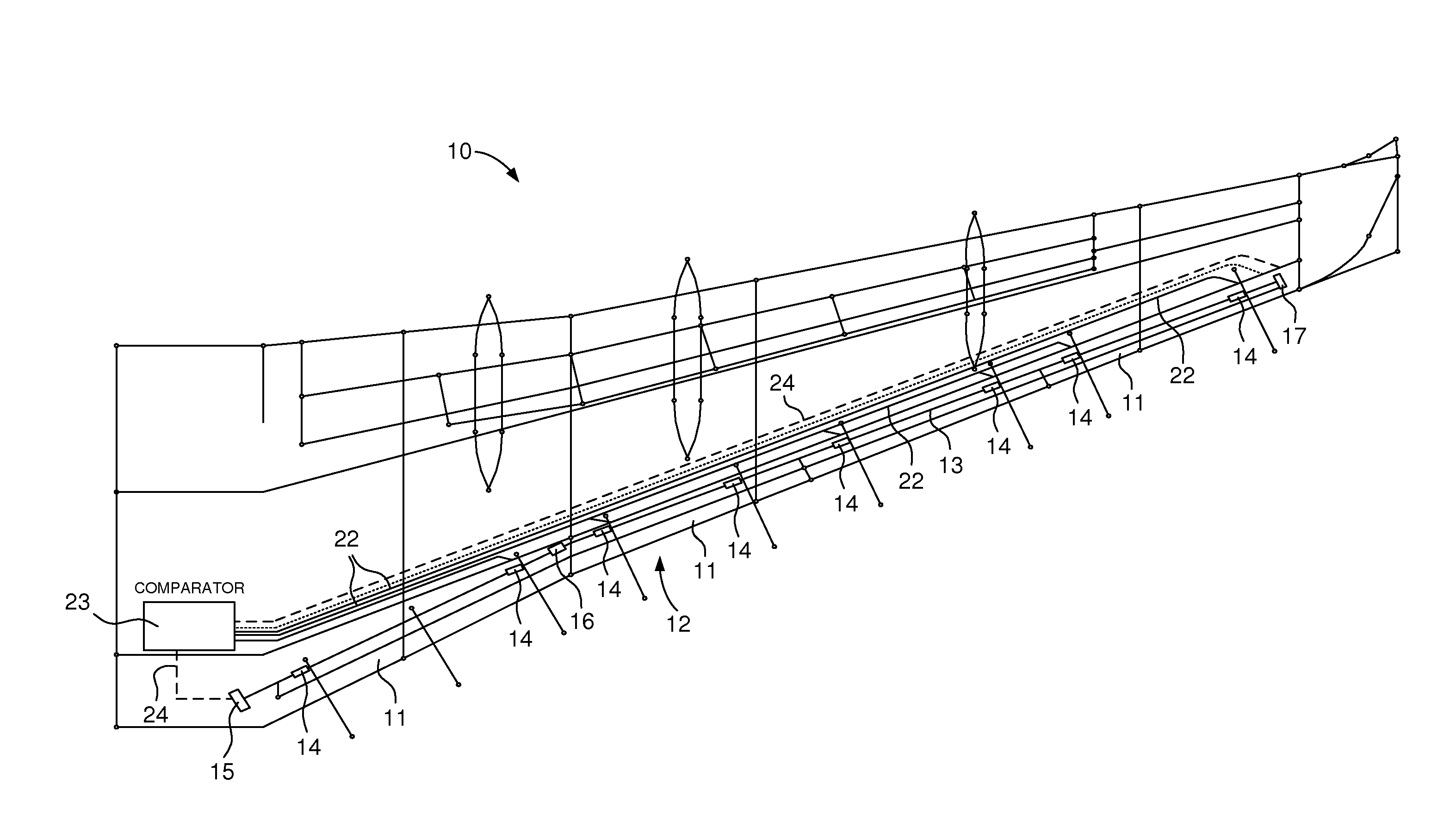
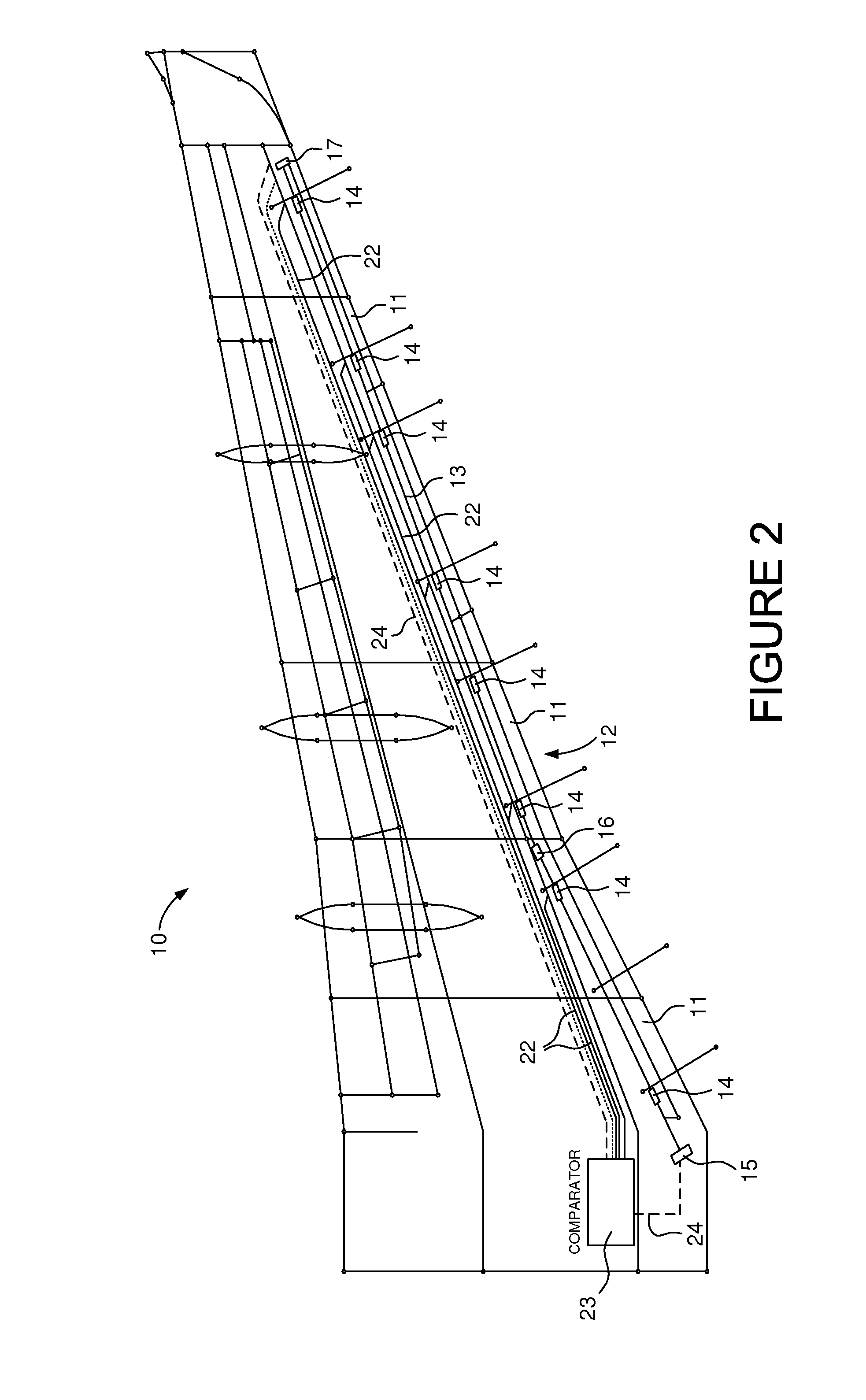
[0037]Referring first to FIG. 2, there is shown a simplified plan view of the inside of an aircraft wing 10 having a plurality of slats 11 along its leading edge 12. A common input drive shaft 13 extends along the length of the wing 10 just inside its leading edge 12 and a rotary actuator 14 is positioned at spaced locations along the length of the common input drive shaft 13. Although the common input drive shaft 13 may be fabricated in sections, those sections are coupled together so that the entire input drive shaft 13 rotates as one in response to rotation of a slat deployment motor 15 located at the inboard end of the wing 1. Two sections of the common input drive shaft 4 may be coupled by a gearbox 16 to accommodate changes in the angle of the wing leading edge 12, which is mirrored by the common input drive shaft 13. Gearbox 16 therefore couples the sections together so that each section may not share the same axis of rotation.

[0038]A wingtip brake 17 may be mounted on the ou...


PUM


Abstract

A system for determining whether the relative rate of deployment of all the slats (11) extending from a leading edge (12) of an aircraft wing (10) is the same as a predetermined relative rate of deployment is disclosed. Each slat includes at least one slat deployment mechanism that includes a drive pinion (8) drivingly coupled to each slat and a rotary actuator (14) having an output shaft (20), the output shaft being driven by a common input drive shaft (13) via the rotary actuator and being coupled to said drive pinion. The system of the invention comprises a sensor (21) associated with each rotary actuator to generate a signal indicative of the rate of rotation of its corresponding output shaft and to supply that signal to a controller (23). The controller is configured to analyse the signals supplied by the sensors and to generate an alarm signal if a relative rate of rotation of all the output shafts differs from a predetermined relative rate of rotation. A method is also disclosed.

Description

[0001]The present invention relates to a slat monitoring system and, in particular, to a system for determining whether the relative rate of deployment of all the slats extending from a leading edge of an aircraft wing is the same as a predetermined relative rate of deployment, within a defined tolerance. A method of determining whether the relative rate of deployment of all the slats extending from a leading edge of an aircraft wing is the same as a predetermined relative rate of deployment, within a defined tolerance, is also disclosed.BACKGROUND[0002]Aircraft need to produce varying levels of lift for take-off, landing and cruise. A combination of wing leading and trailing edge devices are used to control the wing coefficient of lift. The leading edge device is known as a slat. On larger aircraft there may be several slats spaced along the wing edge. During normal flight the slats are retracted against the leading edge of the wing. However, during take-off and landing they are de...

Claims


Application Information

Patent Timeline
Patent Type & Authority Applications(United States)
IPC IPC(8): B64C13/16
CPCB64C9/22B64D2045/001B64D45/0005
Inventor PARKER, SIMON JOHN
Owner AIRBUS OPERATIONS LTD
Why Eureka
Try Eureka