Unlock instant, AI-driven research and patent intelligence for your innovation.

Driver circuit

a technology of driver circuit and lightemitting diode, which is applied in the direction of instruments, light sources, electroluminescent light sources, etc., can solve the problems of degrading the brightness of leds and audible noise according to the direction, and achieve the effect of reducing the ripple of an output voltag

Inactive Publication Date: 2012-12-27
SAMSUNG ELECTRONICS CO LTD
View PDF1 Cites 6 Cited by
  • Summary
  • Abstract
  • Description
  • Claims
  • Application Information

AI Technical Summary

Benefits of technology

The invention provides an LED driver circuit that reduces ripple in the output voltage, even if the load current fluctuates. This is achieved by a booster circuit that generates the LED driving voltage, a voltage detector that divides the output voltage, an error amplifier that compares the detection voltage with a reference voltage, a pulse-width modulation circuit that receives the comparison voltage and outputs a signal based on it, a ripple reduction circuit that outputs a signal based on the detection voltage, and a control signal selector that selects between a pulse-width modulation signal and a fixed logic-level signal as the control signal. The circuit can generate the LED current signal based on a control signal, an LED current signal, and the detection voltage. The ripple reduction circuit can output a signal based on the detection voltage to control the flow of current to the LED array. The switch remains turned on or off depending on the logic level of the LED driving signal. The technical effect of this invention is to reduce ripple in the output voltage of the LED driver circuit, even if the load current fluctuates.

Problems solved by technology

When the ripple of an output voltage relative to a load current exceeds a predetermined value while the LEDs are driven, the slew rate of an LED current may be affected, thereby degrading the brightness of the LEDs.
Also, audible noise may occur according to the magnitude of the ripple of the output voltage.

Method used


Image

  • Driver circuit
  • Driver circuit
  • Driver circuit

Examples


Embodiment Construction

[0029]Hereinafter, the inventive concept will be described in detail by describing exemplary embodiments of the inventive concept with reference to the attached drawings. Like reference numerals in the drawings may denote like or similar elements throughout the specification and the drawings.

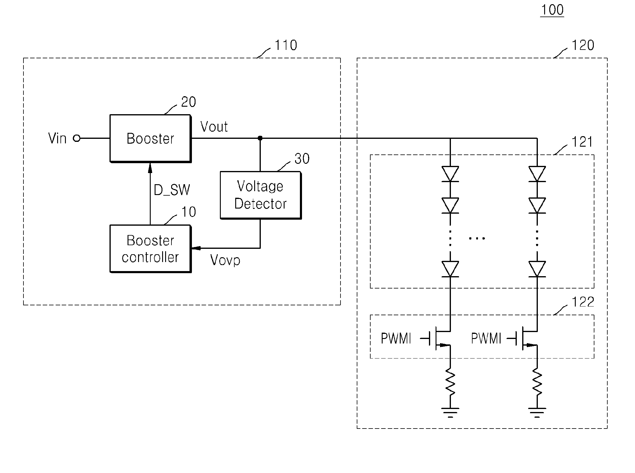
[0030]FIG. 1 is a block diagram of a light-emitting diode (LED) backlight unit (BLU) 100.

[0031]Referring to FIG. 1, the LED BLU includes an LED driver circuit 110 and an LED array unit 120.

[0032]The LED array unit 120 receives an output voltage Vout of a booster 20 and emits or stops emitting light in response to an LED current signal PWMI. The LED array unit 120 includes an LED array 121 including a plurality of LEDs and a switch 122 connected to terminals of the LED array 121 and configured to be turned on and off. The brightness of the LEDs is controlled by turning on and off the switch 122. When the switch 122 is turned on in response to an LED current signal PWMI, a current of about several...


PUM


Abstract

A light-emitting diode (LED) driver circuit configured to generate a constant driving voltage irrespective of a variation in a load current. The LED driver circuit, which may generate an LED driving voltage, may include a booster configured to generate the LED driving voltage in response to a control signal, a voltage detector configured to divide an output voltage of the booster and output a detection voltage, and a booster controller configured to generate the control signal. The booster controller may select one of a pulse-width modulation signal and a fixed logic-level signal as the control signal in response to an LED current signal and the detection voltage and output a selected signal.

Description

CROSS-REFERENCE TO RELATED APPLICATIONS[0001]This application claims priority to Korean Patent Application No. 10-2011-0060798, filed on Jun. 22, 2011, in the Korean Intellectual Property Office, the disclosure of which is incorporated by reference herein in its entirety.TECHNICAL FIELD[0002]Embodiments of the inventive concept relates to driver circuits, and more particularly to light-emitting diode (LED) driver circuits configured to generate a constant driving voltage irrespective of a variation in a load current during the drive of an LED.DISCUSSION OF THE RELATED ART[0003]Recent LCD devices have adopted backlight units (BLUs) using LEDs as light sources instead of cold cathode fluorescent lamps (CCFLs). An LED driver circuit with low load regulation outputs a constant voltage irrespective of a variation in a load current during the driving of the LEDs. When the ripple of an output voltage relative to a load current exceeds a predetermined value while the LEDs are driven, the sl...

Claims


Application Information

Patent Timeline
Patent Type & Authority Applications(United States)
IPC IPC(8): H05B37/02
CPCH05B33/0815H05B45/38H05B45/325H05B45/36H05B45/00H05B45/48H05B45/37
Inventor SEO, MYUNG-HO
Owner SAMSUNG ELECTRONICS CO LTD