Lighting device and illumination apparatus including same

a technology of illumination apparatus and light source, which is applied in the direction of electric variable regulation, process and machine control, instruments, etc., can solve the problem of current being supplied to the solid state light emitting element group deviating from a target value, and achieve the effect of reducing the deviation from a black body locus and improving the color reproducibility of mixed color ligh

Inactive Publication Date: 2012-12-27
PANASONIC CORP
View PDF6 Cites 13 Cited by
  • Summary
  • Abstract
  • Description
  • Claims
  • Application Information

AI Technical Summary

Benefits of technology

[0012]In view of the above, the present invention provides a lighting device capable of reducing a deviation from a black body locus and improving a color reproducibility of a mixed color light of the lights irradiated by solid state light emitting element groups and an illumination apparatus including same.
[0029]As described above, in accordance with the present invention, there is an effect of reducing a deviation from a black body locus and improving color reproducibility of mixed color light of the lights irradiated by solid state light emitting element groups.

Problems solved by technology

However, it is concerned that the current being supplied to the solid state light emitting element group is deviated from a target value due to, e.g., a difference in parts used in the drive circuit or control circuit.

Method used


Image

  • Lighting device and illumination apparatus including same
  • Lighting device and illumination apparatus including same
  • Lighting device and illumination apparatus including same

Examples


first embodiment

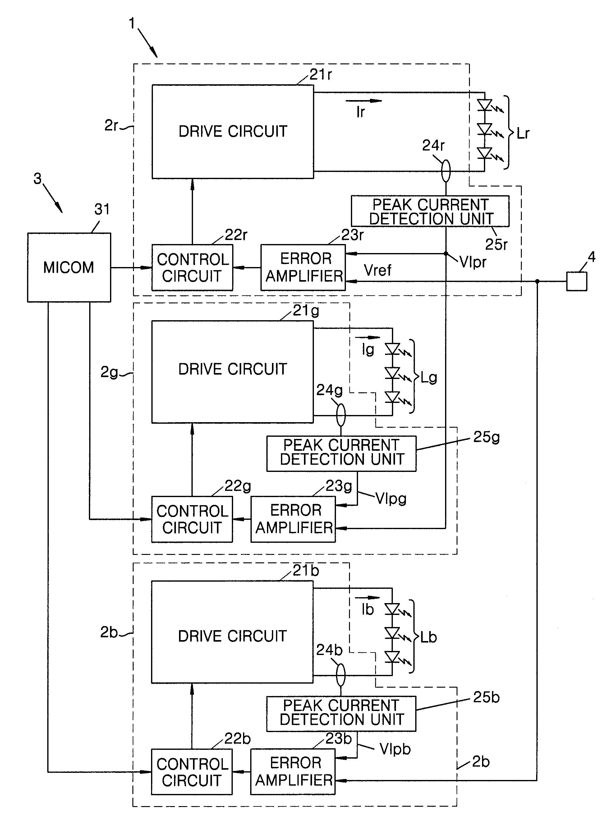
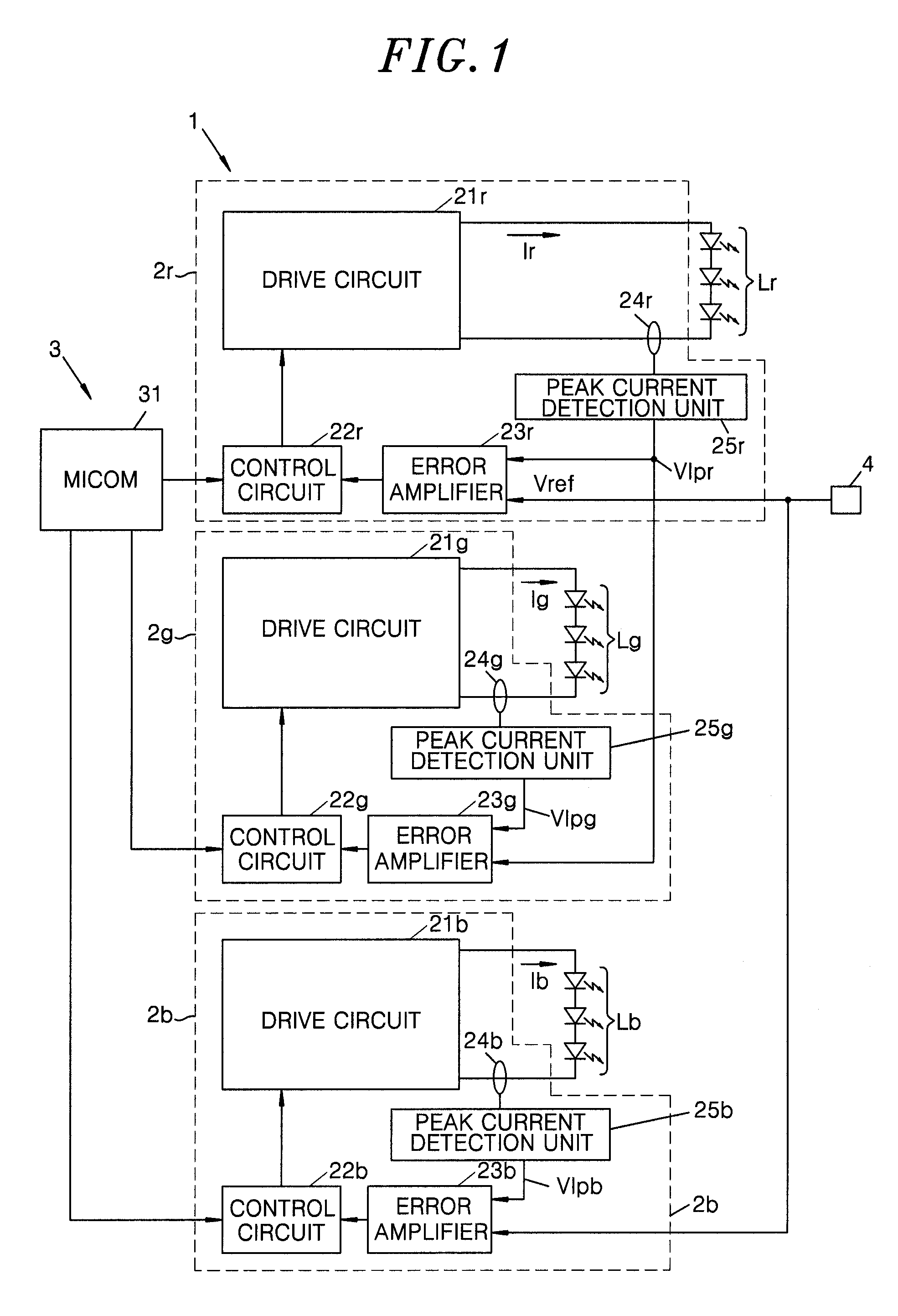
[0051]FIG. 1 illustrates a block diagram of a lighting device 1 in accordance with a first embodiment of the present invention.

[0052]The lighting device 1 of this embodiment turns on a solid state light emitting element group Lr irradiating a red light, a solid state light emitting element group Lg irradiating a green light, and a solid state light emitting element group Lb irradiating a blue light at a predetermined output ratio to irradiate a mixed color light thereof. The solid state light emitting element groups Lr, Lg and Lb, each including an array of three solid state light emitting elements (light emitting diodes), are configured to irradiate the red light, the green light and the blue light, respectively. In addition, if it is not necessary to separately identify each of the solid state light emitting element groups Lr, Lg and Lb, it is referred to as a solid state light emitting element group L. Although the solid state light emitting element group L of this embodiment inc...

second embodiment

[0072]FIG. 3 illustrates a block diagram of a lighting device 1 in accordance with a second embodiment of the present invention. Like reference numerals will be given to like parts common to the first embodiment, and a redundant description thereof will be omitted.

[0073]The lighting device 1 of this embodiment performs an amplitude dimming in which lighting control units 2r, 2g and 2b supply DC currents (steady-state currents) to solid state light emitting element groups Lr, Lg and Lb and control amplitudes of the currents to control outputs from the solid state light emitting element groups Lr, Lg and Lb, respectively. Further, the lighting control units 2r, 2g and 2b control such that an output ratio of the solid state light emitting element groups Lr, Lg and Lb becomes same as a target output ratio.

[0074]A color ratio setting unit 3 of this embodiment includes a MICOM 31, and reference voltage generating units 32r, 32g and 32b.

[0075]The reference voltage generating units 32r and...

third embodiment

[0095]FIG. 7 illustrates a block diagram of a lighting device 1 in accordance with a third embodiment of the present invention. Like reference numerals will be given to like parts common to the second embodiment, and a redundant description thereof will be omitted.

[0096]The lighting device 1 of this embodiment performs an amplitude dimming in which lighting control units 2r, 2g and 2b supply DC currents to solid state light emitting element groups Lr, Lg and Lb and control amplitudes thereof to control outputs from the solid state light emitting element groups Lr, Lg and Lb, respectively. Further, the lighting control units 2r, 2g and 2b control such that an output ratio of the solid state light emitting element groups Lr, Lg and Lb becomes same as a target output ratio.

[0097]The lighting device 1 includes the lighting control units 2r, 2g and 2b, a color ratio setting unit 3, an output control unit 4, an error calculating unit 5, and an adder 6.

[0098]Reference voltage generating un...


PUM


Abstract

A lighting device includes lighting control units respectively provided for controlling lighting of solid state light emitting element groups irradiating light of different chromaticities and a color ratio setting unit for setting a target output ratio of the solid state light emitting element groups. In an xy chromaticity diagram of an XYZ color system, a straight line connecting chromaticity coordinates of lights irradiated by a first and a second solid state light emitting element group intersects a black body locus. Further, the lighting control units include a first and a second lighting control unit for controlling lighting of the first and the second solid state light emitting element group, and the first and the second control unit perform a feedback control such that an output ratio of the second to the first solid state light emitting element group becomes equal to the target output ratio thereof.

Description

FIELD OF THE INVENTION[0001]The present invention relates to a lighting device and an illumination apparatus including same.BACKGROUND OF THE INVENTION[0002]Conventionally, there is a lighting device including three solid state light emitting element groups irradiating light of different chromaticities (a red color, a green color and a blue color), each having a lighting control unit to control lighting of the corresponding solid state emitting element groups (see, e.g., Japanese Patent Application Publication No. 2010-176984). The lighting device varies a chromaticity of a mixed color light from the light emitting element groups by controlling respective outputs from the three solid state light emitting element groups and controlling an output ratio thereof. Further, there is a lighting device in which an illuminance (output) of a mixed color light and a chromaticity of a light can be varied at the same time to obtain a comfortable illumination light.[0003]In the conventional light...

Claims


Application Information

Patent Timeline
Patent Type & Authority Applications(United States)
IPC IPC(8): H05B37/02H05B37/00H05B44/00
CPCH05B33/0866H05B37/02H05B37/0245H05B45/24H05B45/20H05B47/165H05B47/175
Inventor NARUO, MASAHIROIDO, SHIGERUESAKI, SANAHIRAMATU, AKINORI
Owner PANASONIC CORP
Why Eureka
Try Eureka