Imaging apparatus

Inactive Publication Date: 2012-12-27
CANON KK
View PDF8 Cites 16 Cited by
  • Summary
  • Abstract
  • Description
  • Claims
  • Application Information

AI Technical Summary

Benefits of technology

[0008]The present invention has been created to resolve the abovementioned problems inherent to prior art, and it is an object of the present invention to provide a technique making it pos

Problems solved by technology

When imaging of such a subject is performed, since the protective member is present between the specimen and an imaging optical system, the observed image is known to be degraded (decrease in contrast, blurring) due to optical aberration caused by the protective member.
Further, the aberration is apparently caused not only by the protective member located on the slide.
Thus, the aberration in the imaging optical system changes depending on ambient conditions such as temperature.
Typically, there is an unpredictable spread in the thickness of the protective member of a specimen.
Further, the aberration in the imaging optical system can change depending on ambient conditions such as temperature.
Therefore, it is possible that optical aberration de

Method used


Image

  • Imaging apparatus
  • Imaging apparatus
  • Imaging apparatus

Examples


Example

First Embodiment

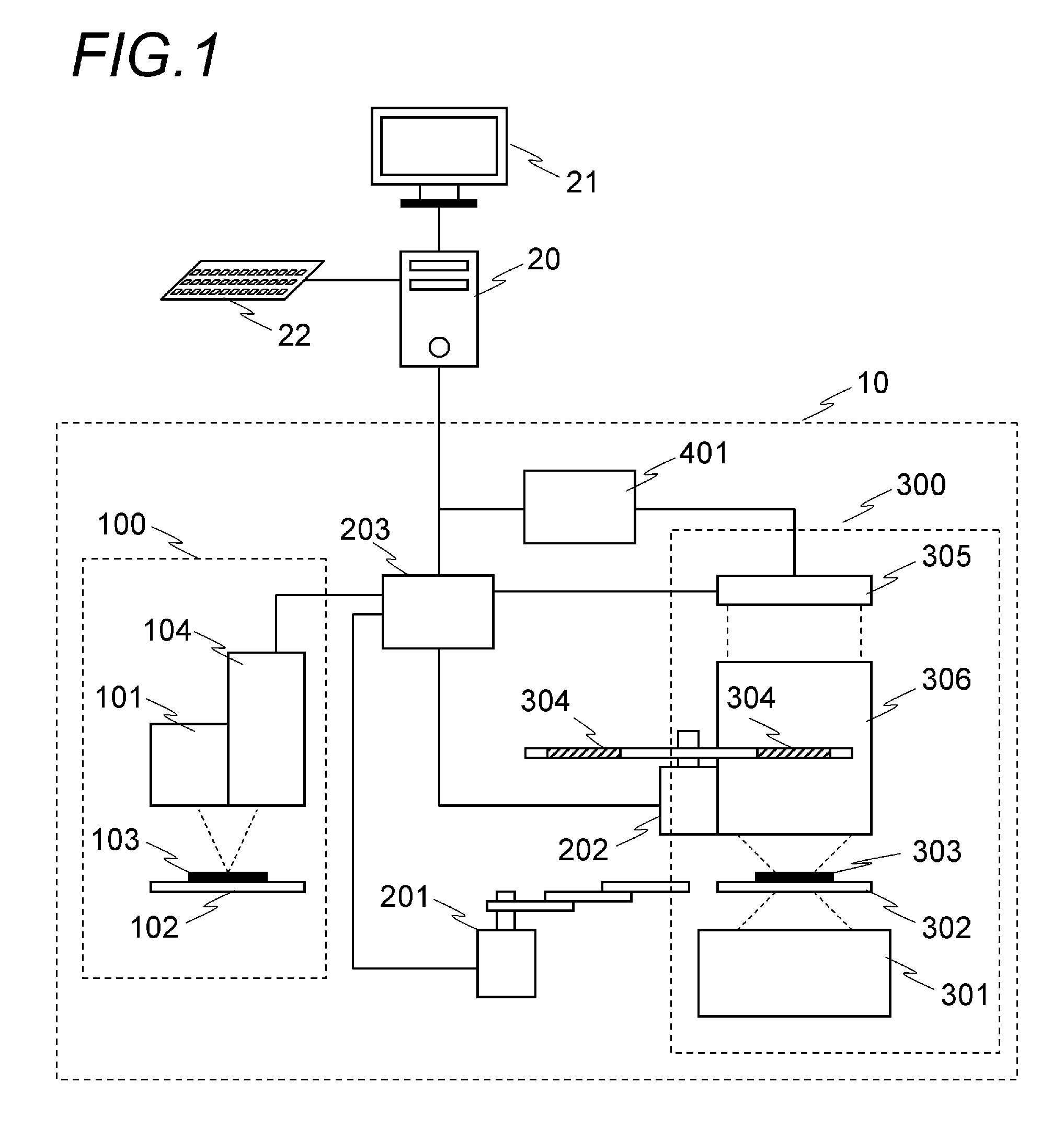
[0040]The first embodiment of the image acquisition method performed in the imaging system shown in FIG. 1 will be explained below. In the explanation below, partial regions obtained by dividing an imaging region will be called subregion; the subregions may overlap each other or be in an exclusive relationship. The information relating to the subregions, such as the positions and dimensions thereof, may be designated by the user prior to imaging. The control unit 203 may store such information as a database in advance. In the configuration of the first embodiment, aberration correction is performed by the optical elements 304 of one kind with respect to one slide. Thus, the method of the present embodiment is applied to the case where the optical elements 304 corresponding to the measurement data of a plurality of subregions on the slide measured by the measuring unit 100 are of one kind only.

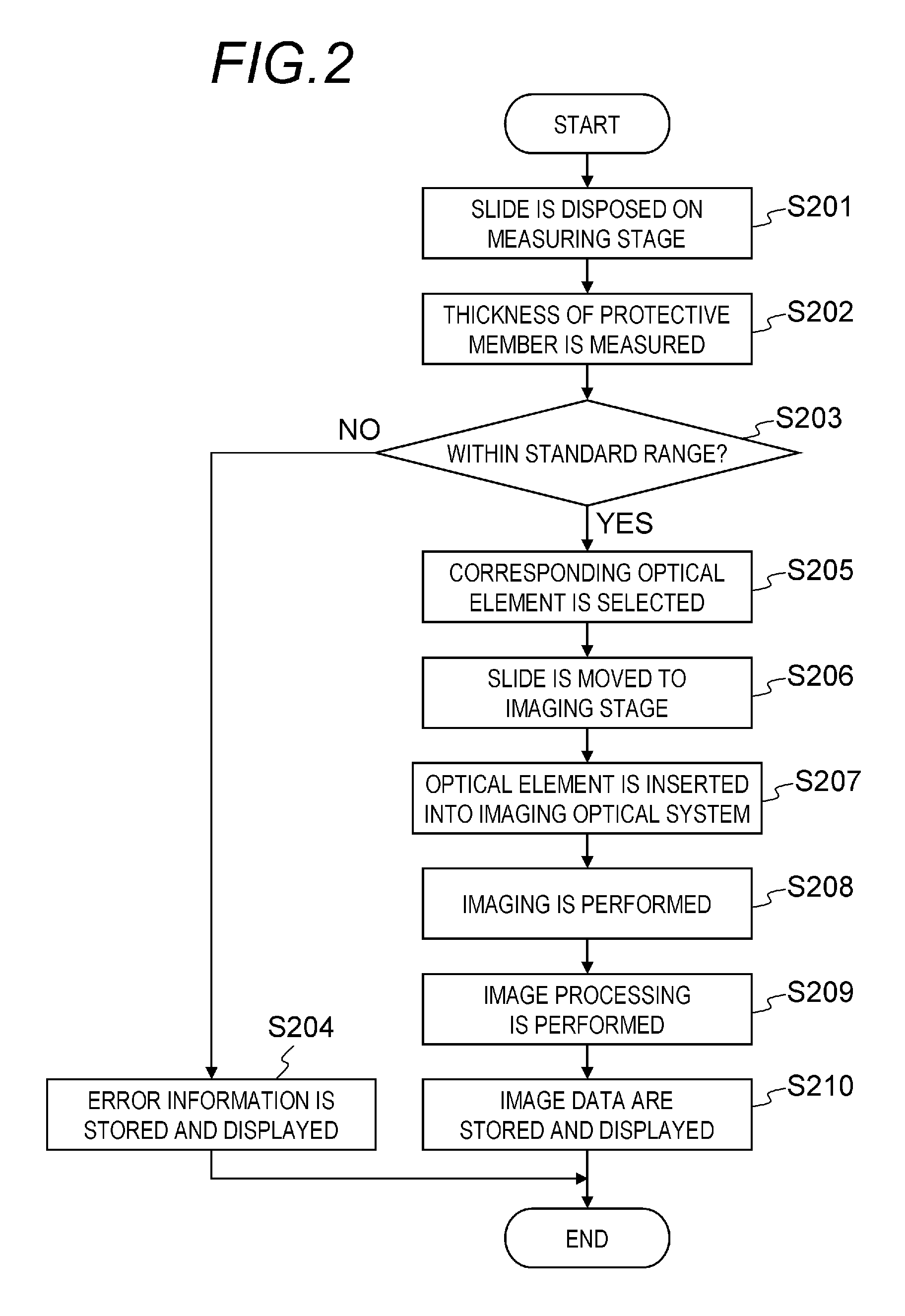
[0041]FIG. 2 is a flowchart illustrating the processing sequence of the fir...

Example

Second Embodiment

[0058]The second embodiment of the image acquisition method in the imaging system shown in FIG. 1 is explained below.

[0059]In the above-described first embodiment, the optical element 304 corresponding to the measurement results obtained for a plurality of points is the same in all of the subregions. However, some protective members have an uneven thickness and the spread in thickness cannot be ignored. Where the imaging by the method of the first embodiment is performed with respect to a specimen covered by such a protective member, an undesirable image is obtained in which regions where the aberration correction has been correctly performed are mixed with regions where such correction has not been performed (over-corrected or under-corrected regions). Accordingly, the processing explained in the second embodiment is performed when the optimum optical element 304 is different for each subregion.

[0060]The processing procedure of the second embodiment is explained wi...

Example

Third Embodiment

[0072]An image acquisition method using the imaging system having the imaging unit shown schematically in FIG. 8A will be explained below as the third embodiment. The imaging unit 300 shown in FIG. 8A is an alternative to the imaging unit 300 shown in FIG. 1. Further, the slide 303, first imaging point, and imaging device 305 are in an optically conjugated relationship with each other. A separate intermediate imaging point may be present in addition to the first imaging point. In the optical system shown in FIG. 8A, an enlarged image of the entire specimen is formed by a first imaging system 307 on a plane including the first imaging point, or in the vicinity of such plane, and an enlarged image of a subregion that is a portion of the enlarged image is formed by a plurality of second imaging systems 309 on a plurality of corresponding imaging devices 305. A similar apparatus configuration can be found, for example, in Japanese Patent No. 4333785. In Japanese Patent N...


PUM


Abstract

An imaging apparatus comprises: an imaging unit having an imaging optical system and an imaging device; a measuring unit that measures, for each of a plurality of regions on a specimen, an optical aberration or a physical quantity causing the aberration before the imaging of the specimen is performed; a plurality of optical elements that are inserted in an optical path of the imaging optical system for correcting the aberration and that differ in correction amount; and a control unit that selects an optical element from among the optical elements on the basis of a measurement result of the measuring unit, and inserts the selected optical element into the optical path of the imaging optical system before the imaging of the specimen. The imaging optical system is configured to be capable of forming simultaneously images of the plurality of regions on the imaging device.

Description

BACKGROUND OF THE INVENTION[0001]1. Field of the Invention[0002]The present invention relates to an imaging apparatus that performs imaging of a specimen and acquires a digital image.[0003]2. Description of the Related Art[0004]An imaging apparatus that performs imaging of a microscope image such as a tissue slice of a human body and enables the accumulation and observation of digital image data has recently attracted much attention in the field of pathological diagnostic. In the imaging apparatus of this kind, a configuration (slide) in which a specimen, which is an observation object, is covered and fixed by a transparent protective member (cover glass) is typically used as a subject. When imaging of such a subject is performed, since the protective member is present between the specimen and an imaging optical system, the observed image is known to be degraded (decrease in contrast, blurring) due to optical aberration caused by the protective member. Further, the aberration is app...

Claims


Application Information

Patent Timeline
IPC IPC(8): H04N5/217H04N7/18
CPCG02B21/365G02B27/0068H04N5/3572H04N25/61G02B13/18
Inventor HIGAKI, YOSHINARIKAWASHIMA, MIYOKOTSUJI, TOSHIHIKO
Owner CANON KK
Why Eureka
Try Eureka