Liquid crystal display device

a display device and liquid crystal technology, applied in non-linear optics, instruments, optics, etc., can solve the problems of deterioration of display properties, deterioration of impact resistance, etc., to prevent lowering of display quality, improve impact resistance, and improve reliability

Active Publication Date: 2012-12-27
DAI NIPPON PRINTING CO LTD
View PDF5 Cites 6 Cited by
  • Summary
  • Abstract
  • Description
  • Claims
  • Application Information

AI Technical Summary

Benefits of technology

[0046]In the present invention, the transparent substrate having rigidity is bonded to the viewing-side surface of the liquid crystal panel with the fusion bonding layer being interposed therebetween. Thus, there are exhibited effects that the impact resistance is improved and reliability is enhanced and that it is possible to prevent lowering in the display quality, the lowering being due to bonding of the liquid crystal panel and the transparent substrate with the fusion bonding layer interposed therebetween. Furthermore, in the present invention, by placing functional layers such as the light diffusion layer, the louver layer, and the light-absorbing layer, effects are exhibited that display defects such as unevenness are decreased and that improvement of the contrast and the like become possible, thus enabling improvement in the display quality.

Problems solved by technology

On the display surface of the liquid crystal panel, a thin functional film is in an exposed state and, therefore, is vulnerable to external impact.
When impact is applied to the liquid crystal panel, the liquid crystal panel may be destroyed, or alignment of the liquid crystals may become disordered and alignment defects may occur, resulting in deterioration of the display properties.

Method used


Image

  • Liquid crystal display device
  • Liquid crystal display device
  • Liquid crystal display device

Examples


example 1

(1) Preparation of Thermoplastic Resin

[0197]To a vinyl acetate copolymer (vinyl acetate content: 28 weight %, MFR: 15 g / 10 minutes), there were added 0.3 weight part of a silane coupling agent (methacryloxypropyltrimethoxysilane) and, further, 0.2 weight part of an antioxidant. The mixture was kneaded to obtain a thermoplastic resin.

(2) Manufacture of Fusion Bonding Film

[0198]The above-described thermoplastic resin was molded using a 150 mmφ extruder and a film molding machine with a 1000 mm wide T dice at a resin temperature of 90° C. and at a take-up speed of 5 m / min to obtain a 300 μm thick film-like fusion bonding layer.

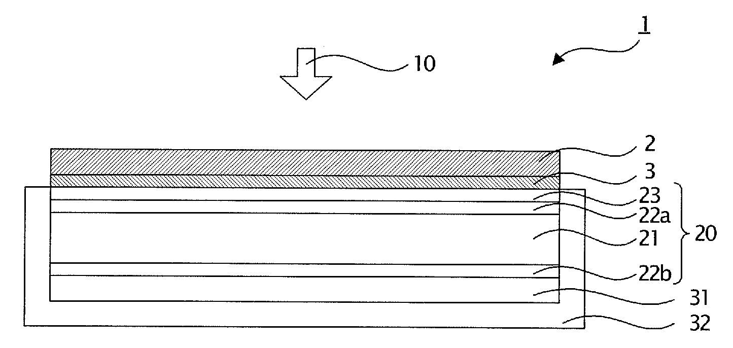
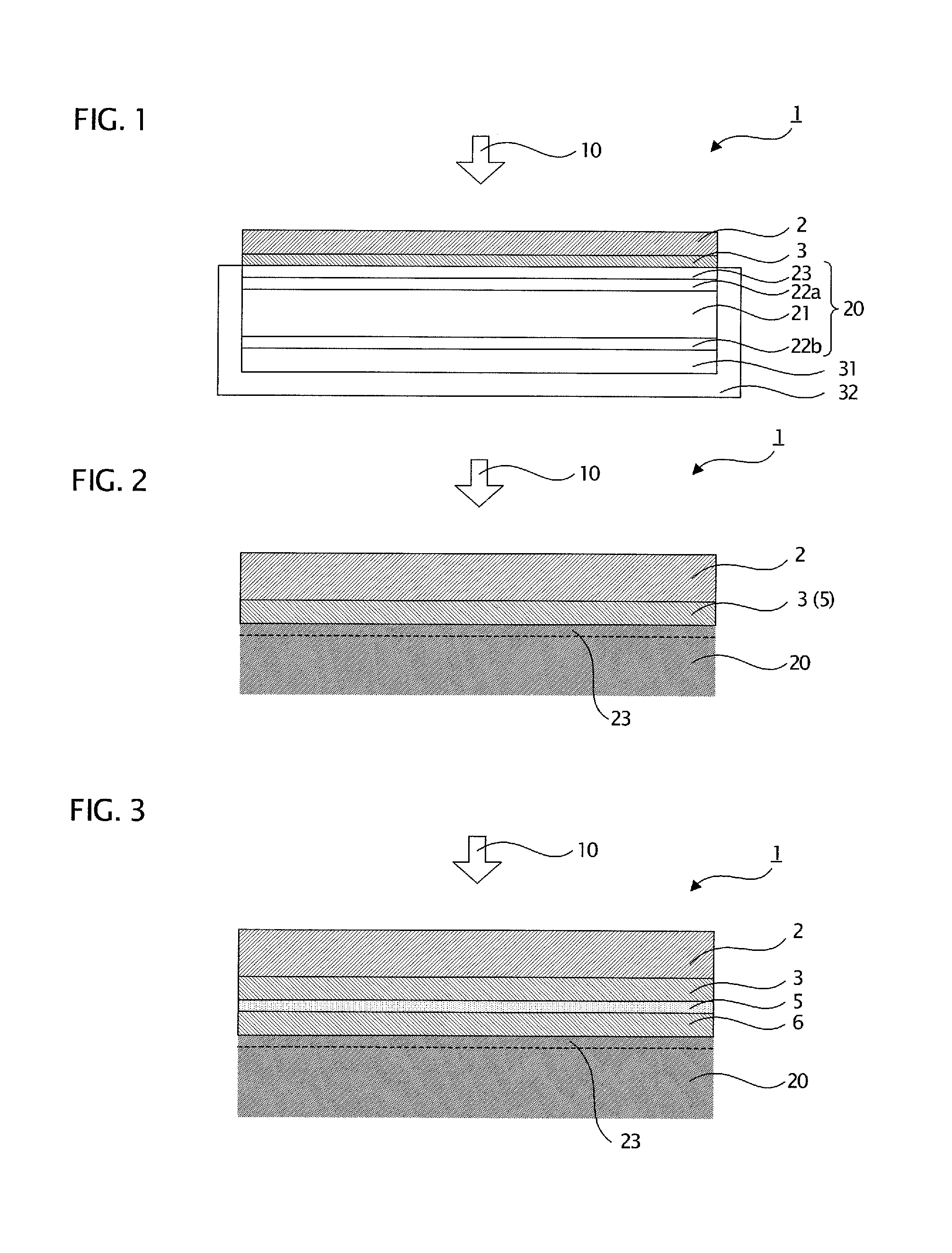
(3) Bonding of Glass Substrate / Fusion Bonding Film / Liquid Crystal Panel

[0199]The above-described fusion bonding film was sandwiched between a glass plate (922 mm×542 mm) and a liquid crystal panel (920 mm×540 mm) with a horizontal pixel pitch of 0.2 mm, the liquid crystal panel being positioned within the periphery of the glass plate, and laminated under vacuum t...

example 2

(1) Preparation of Thermoplastic Resin

[0201]To a vinyl acetate copolymer (vinyl acetate content: 10 weight %, MFR: 25 g / 10 minutes), there were added 0.3 weight part of a silane coupling agent (methacryloxypropyltrimethoxysilane) and, further, 0.2 weight part of an antioxidant. The mixture was kneaded to obtain a thermoplastic resin with a refractive index of 1.462.

(2) Manufacture of Fusion Bonding Film

[0202]The above-described thermoplastic resin was molded using a 150 mmφ extruder and a film molding machine with a 1000 mm wide T dice at a resin temperature of 120° C. and at a take-up speed of 30 m / min to obtain a 50 μm thick film-like fusion bonding layer.

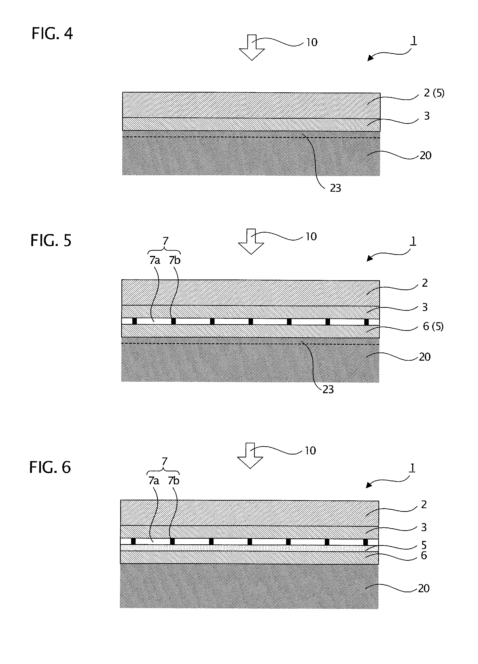
(3) Manufacture of Fusion Bonding Film / Film with Light Diffusion Layer / Fusion Bonding Film

[0203]First, a resin composition for a light diffusion layer, comprising 27.5 weight parts of acryl-styrene beads (particle size: 4 μm, refractive index: 1.520) added to 100 weight parts of a UV curable resin (refractive index: 1.520), was c...

example 3

[0205]A liquid crystal display device was fabricated in the same manner as in Example 2 except that, in preparation of the film with a light diffusion layer of Example 2, acryl-styrene beads having a refractive index of 1.525 were used.


PUM

PropertyMeasurementUnit
thicknessaaaaaaaaaa
thicknessaaaaaaaaaa
refractive index ratioaaaaaaaaaa

Abstract

A main object of the present invention is to provide a liquid crystal display device having high impact resistance and good display properties. In the present invention, the above-described object is attained by providing a liquid crystal display device comprising a liquid crystal panel, a transparent substrate having rigidity, and a fusion bonding layer comprising a thermoplastic resin, characterized in that the transparent substrate is bonded to a viewing-side surface of the liquid crystal display panel with the fusion bonding layer interposed therebetween.

Description

FIELD OF THE INVENTION[0001]The present invention relates to a liquid crystal display device having a protected surface and having high impact resistance as well as good display properties.BACKGROUND ART[0002]In general, the liquid crystal display device has a structure where the periphery of a liquid crystal panel is protected by a housing, the liquid crystal panel having liquid crystal sandwiched between two thin substrates on which members such as an alignment films and electrodes are formed, and the panel having functional films such as a light guide plate, a polarizer, and further an anti-glare film and an anti-reflection film piled in layers. On the display surface of the liquid crystal panel, a thin functional film is in an exposed state and, therefore, is vulnerable to external impact. When impact is applied to the liquid crystal panel, the liquid crystal panel may be destroyed, or alignment of the liquid crystals may become disordered and alignment defects may occur, result...

Claims


Application Information

Patent Timeline
Patent Type & Authority Applications(United States)
IPC IPC(8): G02F1/1335
CPCG02F1/133308G02F2201/503G02F2001/133331G02F1/133331G02F1/1333G02F1/1335
Inventor HONDA, MAKOTONAKAMURA, NORINAGA
Owner DAI NIPPON PRINTING CO LTD
Why Eureka
Try Eureka