System for machining a bevel

a technology of machining system and bevel, which is applied in the field of lapidary system, can solve the problems of requiring subsequent brushing, slow performance, and slivers of material, and achieve the effect of reducing the discard rate and speeding up the manufacturing process

Active Publication Date: 2012-12-27
COMADUR
View PDF24 Cites 6 Cited by
  • Summary
  • Abstract
  • Description
  • Claims
  • Application Information

AI Technical Summary

Benefits of technology

[0004]It is an object of the present invention to overcome all or part of the aforementioned drawbacks, by proposing a system for machining a bevel which speeds up manufacture and which reduces the discard rate.

Problems solved by technology

This technique is widely used but is slow to perform, regularly causes chips (slivers of material) and requires subsequent brushing.

Method used


Image

  • System for machining a bevel
  • System for machining a bevel
  • System for machining a bevel

Examples


Embodiment Construction

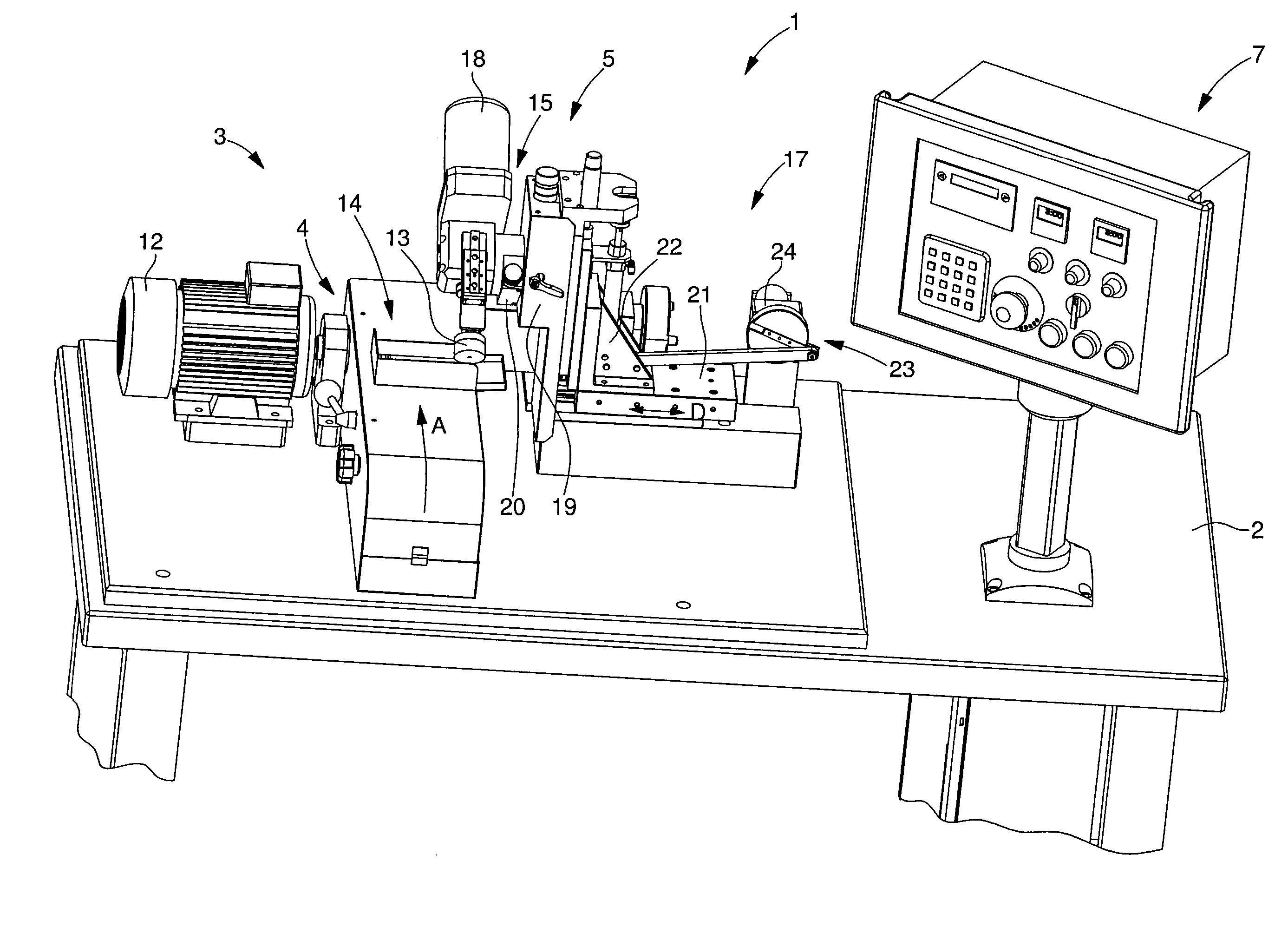
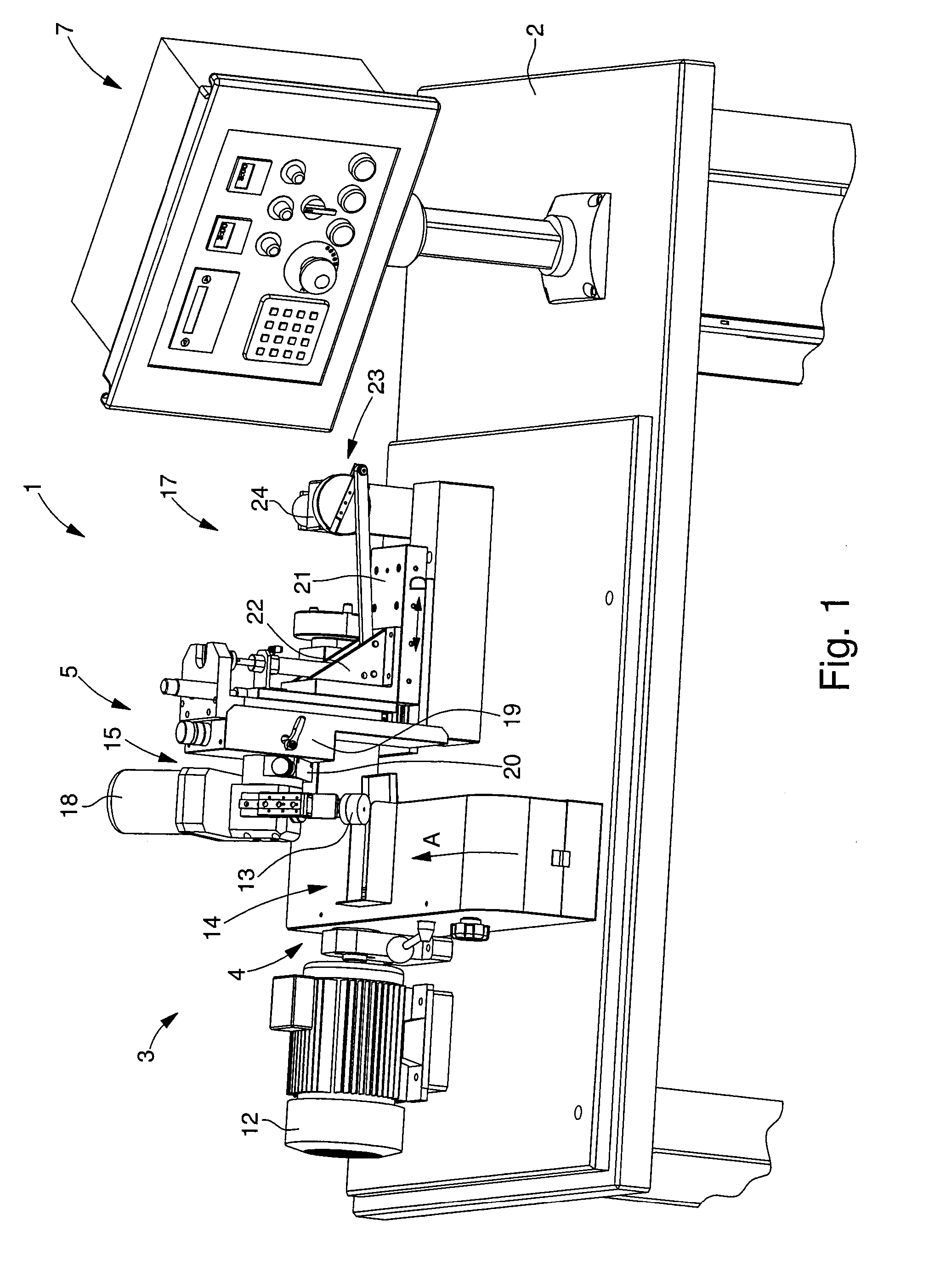
[0023]As illustrated in FIG. 1, the invention relates to a system 1 for machining a bevel 32, 34 for a disk shaped part 31 made of hard material such as corundum. According to the invention, part 31 may be intended to form a spherical timepiece crystal.

[0024]Machining system 1 includes a grinding device 3, a device 5 for securing the part and a control device 7 for controlling the actuators of system 1. All of the devices are mounted on a frame 2.

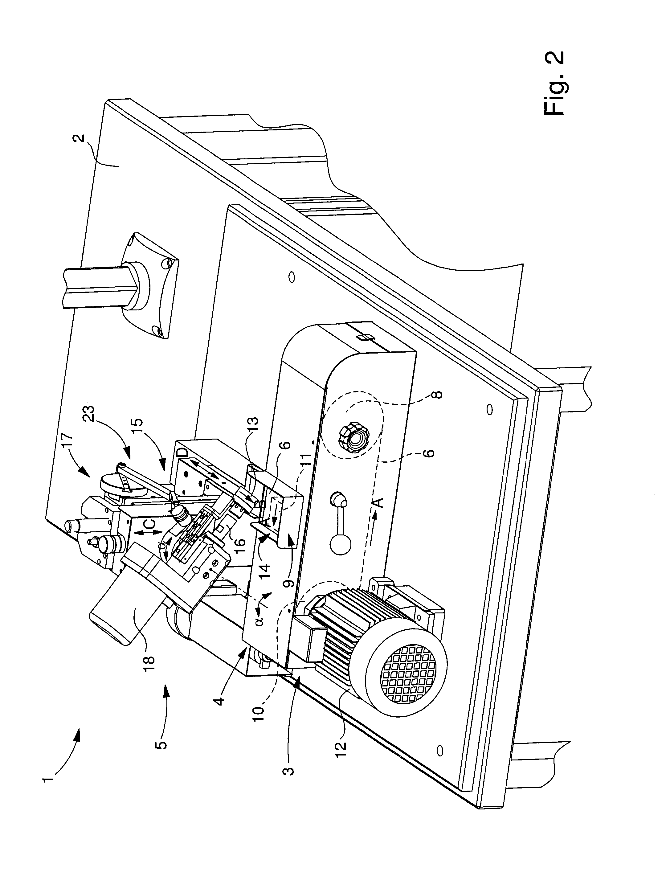
[0025]According to the invention, grinding device 3 includes an abrasive means 4 which is preferably moveable so as to improve machining. As visible in FIG. 2, abrasive means 4 is formed by an abrasive strip 6 rotatably mounted on two rollers 8, 10 and driven by an actuator 12 in motion A. As visible in FIGS. 1 to 3, grinding device 3 includes a restricted area 14 in which abrasive means 4 is accessible and protected by vertical walls to limit blasting of material and to safeguard operations.

[0026]Advantageously according to the invention, ...


PUM


Abstract

The invention relates to a system (1) for machining a bevel (32, 34) on a disk shaped part (31) including a grinding device (3) having abrasive means (4), a device (5) for securing the part (31) including a support (13) to which said part is fitted and which is integral with an axis of rotation (16). According to the invention, the securing device (5) further includes a means (15) of orienting the axis (16) of rotation (B) to define the angle of said one bevel (32, 34) and a means (17) of moving the support (13) closer to the abrasive means (4) in order to machining the part (13) under stress.
The invention concerns the field of crystals for timepieces.

Description

[0001]This application claims priority from European Patent Application No. 11171314.5 filed Jun. 24, 2011, the entire disclosure of which is incorporated herein by reference.FIELD OF THE INVENTION[0002]The invention relates to a lapidary system for a part made of hard material such as corundum and, more specifically, a system of this kind for forming a bevel.BACKGROUND OF THE INVENTION[0003]Watch crystal bevels are generally formed by a grinding wheel which moves tangentially at the bevel angle against the edge of the part to be cut. This technique is widely used but is slow to perform, regularly causes chips (slivers of material) and requires subsequent brushing.SUMMARY OF THE INVENTION[0004]It is an object of the present invention to overcome all or part of the aforementioned drawbacks, by proposing a system for machining a bevel which speeds up manufacture and which reduces the discard rate.[0005]The invention therefore relates to a system for machining a bevel on a disk shaped ...

Claims


Application Information

Patent Timeline
Patent Type & Authority Applications(United States)
IPC IPC(8): B24B9/08B24B13/00
CPCB24B9/085G04D3/065B24B21/002
Inventor TASSETTI, JEAN-PAULVUILLEMIN, CHRISTOPHEBEZ, FABIEN
Owner COMADUR
Why Eureka
Try Eureka