Pitman of a jaw crusher, jaw crusher, crushing plant and crushing method

a technology of crushing plant and jaw crusher, which is applied in the field of pitman of a jaw crusher, a jaw crusher and a crushing plant and a crushing method, can solve the problems of increasing the cost and dynamic force, difficult to check and correct casting and quality errors in enclosed pitman, and bending of the pitman and the wear part, so as to reduce or remove the bending and distortion, the effect of eliminating bending and distortion

Active Publication Date: 2013-02-21
METSO OUTOTEC (FINLAND) OY
View PDF10 Cites 4 Cited by
  • Summary
  • Abstract
  • Description
  • Claims
  • Application Information

AI Technical Summary

Benefits of technology

[0022]A cross-sectional support arranged in the honeycomb structure reduces or removes bending of the pitman and the wear part compared with a known pitman, which has poorer horizontal rigidity. The cross-sectional supports eliminate bending and distortion horizontally. The cross-sectional support may reduce support span which is in the pitman in the back of the wear part. The pressing work in a crushing event is better focused in breaking the stone and not in the transformation (elasticity) of the pitman. Thus the stone may be crushed with smaller stroke count and smaller stroke length. The capacity of the crusher and the crushing plant may be increased because the mineral material is crushed and does not stay waiting for a new stroke. Crushing work done by a smaller stroke also affects other components of the crusher which may be lightened if needed. If needed, the mass of the flywheel and the counterweight of the crusher may be reduced. The power source may be smaller in power, as well. The amount of the energy engaged in the flywheel may be reduced. The environment is less burdened because of savings in material and energy. If a known amount of material is used the structure may be made more durable and more rigid.
[0023]The quality of manufacturing the pitman may be improved. There are less work phases and the manufacturing may be speeded up. When casting no cores (web) are needed which cause differences in wall thickness and additional costs. In manufacturing the pitman less material is needed which reduces the mass of the pitman. Weight may also be reduced by machining the edges of the webs because the machining surface has significantly higher fatigue strength than the casting surface. The casting is more easily done. In the manufacturing, a considerably better end quality may be achieved and the wall thicknesses are easily checked and the weight of the pitman optimized. The openness makes it easy to check and fix casting defects. Casting defects may be removed by grinding from the web edges which are critical in tension. Sand cleaning holes are not needed and the sand removal phase is left out.
[0024]Holes formed in the structure because of casting may be avoided by an open structure of the pitman. Thus strength-weakening stress peaks caused by crushing forces may be diminished in the structure. The hole for the intermediate rod may be made entirely by machining, in which case the fatigue strength of the structure is better than in case of the non-machined surface generated after casting. In that case one may get rid of the residual tensions of the hole, as well. Additionally, the location of the hole for the intermediate rod may be better chosen when in a whole less residual tension remains in the pitman than in the known pitman.

Problems solved by technology

The moving of cores during casting has lead to differences in wall thicknesses of the webs, because of which the wall thickness of the castings have to be oversized, which adds to the cost and dynamic forces.
It is difficult to check and correct casting and quality errors in an enclosed pitman.
Sand removal through exhaust openings after the casting is laborious and time consuming.
This increases the mass of the pitman, which increases dynamic forces.
The transformations increase power requirement and reduce crushing capacity.
Additionally, the material in the pitman is exposed to fatigue, especially in the area of the supporting point of the toggle plate.
It is known that the hole for the intermediate rod is non-machined and the hole with cast surface is sensitive to crack formation.
A cross-sectional support arranged in the honeycomb structure reduces or removes bending of the pitman and the wear part compared with a known pitman, which has poorer horizontal rigidity.
When casting no cores (web) are needed which cause differences in wall thickness and additional costs.
Thus strength-weakening stress peaks caused by crushing forces may be diminished in the structure.

Method used


Image

  • Pitman of a jaw crusher, jaw crusher, crushing plant and crushing method
  • Pitman of a jaw crusher, jaw crusher, crushing plant and crushing method
  • Pitman of a jaw crusher, jaw crusher, crushing plant and crushing method

Examples


Embodiment Construction

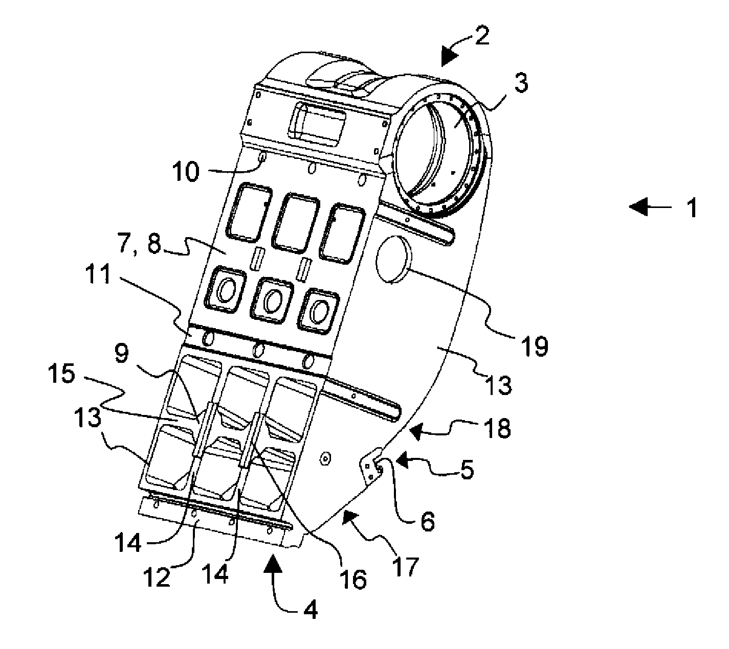
[0032]In the following description like reference signs denote like parts. It should be realized that the presented figures are not in scale as a whole, and they serve merely to illustrate the embodiments of the invention.

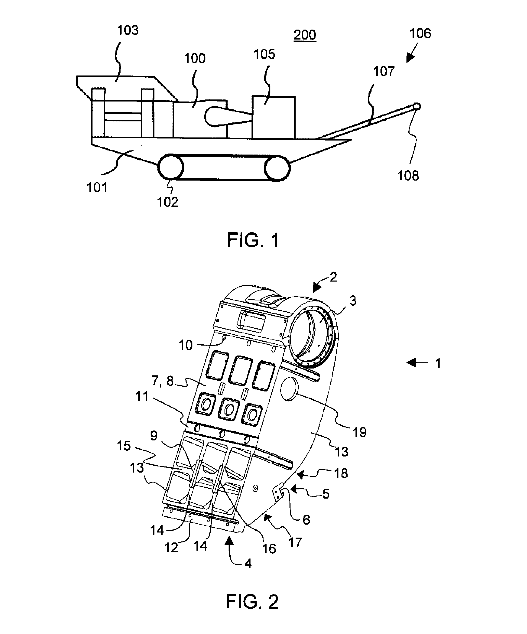
[0033]In FIG. 1, there is presented a processing apparatus of mineral material, a crushing plant 200 comprising a jaw crusher 100. In the crushing plant 200, there is a feeder 103 for feeding material into the jaw crusher 100 and a belt conveyor 106 for transferring crushed material further from the crushing plant.

[0034]The belt conveyor 106 presented in FIG. 1 comprises a belt 107 arranged to proceed around at least one drum 108. The crushing plant 200 also comprises a power source and a control centre 105. The power source may be for instance a diesel or electric motor, which provides energy to be used by process units and hydraulic circuits.

[0035]The feeder 103, the crusher 100, the power source 105 and the conveyor 106 are attached to the body 101 of the crushi...


PUM


Abstract

A pitman of a jaw crusher comprising an upper part, which comprises an upper supporting point for supporting the pitman in the body of the jaw crusher, and a lower part comprising a lower supporting point for supporting the pitman in the body of the jaw crusher through a toggle plate. The lower part of the pitman comprises sidewalls and honeycomb structure open to the crushing direction, which structure comprises one or more cross-sectional supports reaching from the first sidewall of the pitman to the second sidewall. A jaw crusher, a crushing plant and a method for increasing crushing capacity of mineral material.

Description

FIELD OF THE INVENTION[0001]The invention relates to a pitman of a jaw crusher, a jaw crusher and a crushing plant and a crushing method, which are suitable for crushing mineral material.BACKGROUND OF THE INVENTION[0002]The function of the jaw crusher is based on the force pressing stone, the jaw moving in respect of an eccentric shaft moves back and forth regarding the fixed jaw. Movable jaws i.e. pitmans of the jaw crushers have been produced in various different ways. A casted pitman is enclosed i.e. closed in its cross-sectional profile. In the patent publication EP1049539B1, there is presented a jaw crusher with a pitman with closed cross-sectional profile.[0003]Manufacturing a pitman according to a closed profile requires several different work phases. When casting, cores are needed for manufacturing closed profile parts. The moving of cores during casting has lead to differences in wall thicknesses of the webs, because of which the wall thickness of the castings have to be ov...

Claims


Application Information

Patent Timeline
Patent Type & Authority Applications(United States)
IPC IPC(8): B02C1/10B02C19/00B02C21/00B02C1/02
CPCB02C1/10
Inventor SUTTI, RISTOJONKKA, JARI
Owner METSO OUTOTEC (FINLAND) OY
Why Eureka
Try Eureka