
Turning mechanism in machining of large ship propeller shafts

A technology for stern shafts and ships, which is applied in the field of turning devices in the processing of large ship stern shafts. It can solve the problems of inability to increase the rigidity of parts, improper pressure of parts, and reduced processing accuracy, so as to reduce friction and heat generation during cutting, and reduce heat generation. The effect of increasing the turning speed

Inactive Publication Date: 2012-01-18
ZHEJIANG WANLIANDA MACHINERY MFG
View PDF4 Cites 7 Cited by
  • Summary
  • Abstract
  • Description
  • Claims
  • Application Information

AI Technical Summary

Problems solved by technology

However, if the two supporting blocks of the tool holder support the workpiece, the pressure on the part is not appropriate, and the machining accuracy will still be affected.
If the pressure is too small or there is no contact, it will not work, and the rigidity of the part cannot be improved: if the pressure is too high, the part will be pressed against the turning tool, and the cutting depth will increase, which will cause a series of problems that reduce the machining accuracy
Some people also proposed the process of reverse cutting, but the above-mentioned possible bending deformation caused by the cutting accuracy problem still exists

Method used


Image

  • Turning mechanism in machining of large ship propeller shafts
  • Turning mechanism in machining of large ship propeller shafts
  • Turning mechanism in machining of large ship propeller shafts

Examples


Embodiment Construction

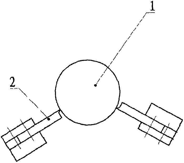
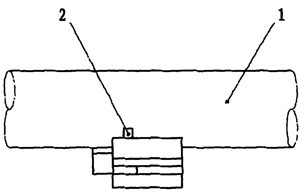
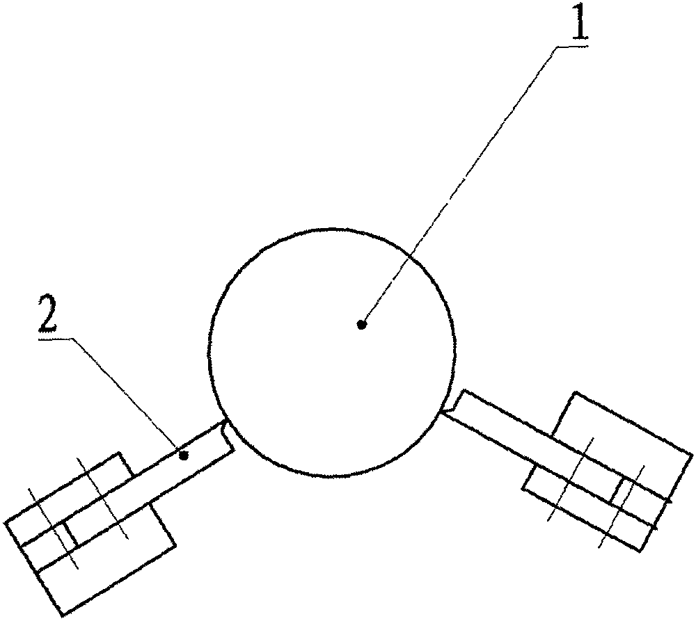
[0010] A turning device in the processing of a large ship stern shaft is a lathe with a chuck at the head of the bed, a thimble at the end of the bed, and a center support. An axial feed mechanism is installed on the bed rail. A knife rest is respectively installed on the radial feed mechanism, and a follower rest is also installed on the axial feed mechanism. The installation position of the tool holder relative to the stern shaft is as follows: figure 1 , 2 As shown, the feeding direction of the turning tool 2 on the two tool holders points to the axis of the stern shaft 1 from downward obliquely upward, and each is on the radial line of 60° between the vertical plane of the axis. At the same time, the two turning tools There is a gap in the length direction of the shaft, that is, there are front and rear for the cutting point of the shaft. The emitters of the three laser rangefinders point to the axis of the stern shaft, which are in the same direction as the feed directi...


PUM


Abstract

The invention provides a turning mechanism in the machining of large ship propeller shafts, wherein the turning mechanism is provided with two tool holders (2), the feeding directions of turning tools on the two tool holders are oblique and upward relative to a propeller shaft (1), the turning tools are symmetric according to a vertical plane passing the axis, and the two tool holders are mounted on the same axial feed mechanism and respectively provided with a radial feed mechanism. The turning mechanism provided by the invention uses the two turning tools, the feeding directions of the turning tools are oblique and upward relative to the propeller shaft, and the turning tools are symmetrically arranged at both sides of a workpiece. Compared with the prior art, the turning mechanism ensures that the bending effect applied on the shaft by the cutting force of the turning tools and the gravity of the shaft can be dispersed and counteracted, the bending effect applied on the shaft by gravity and cutting force can be eliminated under the condition that the amount of radial feed is controlled, and thereby the turning precision is increased. Meanwhile, under the circumstance of double-tool cutting, the amount of feed of a single turning tool can be reduced, so that the friction and cutting heat of the workpiece can be reduced, and if the amount of feed is controlled at more than half of the ordinary amount of feed, then the turning speed can be increased as well on the basis of heat reduction.

Description

technical field [0001] The invention relates to a turning device for machining a large ship stern shaft. Background technique [0002] Turning in the processing of large ship stern shafts has the same problems as the turning process of slender shafts. The main reason is that the workpiece is large in length, and it is easy to bend and deform due to cutting force and gravity, resulting in vibration, which affects the processing accuracy and surface quality. roughness. Therefore, in the machining of such slender shafts, it is necessary to install a center support and sometimes a tool rest to counteract the cutting force and gravity on the bending of the shaft. However, if the two supporting blocks of the tool holder support the workpiece, the pressure on the part is not appropriate, and the machining accuracy will still be affected. If the pressure is too small or there is no contact, it will not work, and the rigidity of the part cannot be improved: if the pressure is too h...

Claims


Application Information

Patent Timeline
Patent Type & Authority Applications(China)
IPC IPC(8): B23B5/08
Inventor 来文光
Owner ZHEJIANG WANLIANDA MACHINERY MFG
Learn More