
Blood vessel catheter and injection system for carrying out a blood pressure measurement of a patient

blood vessel technology, applied in the field of blood vessel catheter and injection system for carrying out a blood pressure measurement of a patient, can solve the problems of inability to control and adjust the zero point pressure of the tip manometer, the pressure signal is falsified by the transfer characteristic of the long transfer tube system, and the inability to carry out a blood pressure measurement. accurate and continuous

Active Publication Date: 2012-12-27
EDWARDS LIFESCIENCES IPRM AG
View PDF1 Cites 3 Cited by
  • Summary
  • Abstract
  • Description
  • Claims
  • Application Information

AI Technical Summary

Benefits of technology

"The present invention provides a blood vessel catheter and a fluid transfer system that can accurately and continuously measure the blood pressure of a patient. The catheter has a pressure sensor located close to the patient's body, reducing damping or resonance of the pressure signal. The catheter is disposable and can be releasably coupled to a fluid transfer unit. The fluid transfer system includes a control valve that can be operated remotely, allowing for remote control of fluid flow through the catheter. The system also includes a pneumatic or hydraulic valve activation signal, a valve adapted to control the fluid flow, and a remote valve control element for providing the valve activation signal. The system further includes a reservoir for rinsing the catheter, a fluid flow means, and a stop cock for controlling the fluid flow. The system allows for continuous measurement of blood pressure and is convenient for use in rinsing, injecting, or drawing blood samples."

Problems solved by technology

The disadvantage of this system is that the pressure signal is falsified by the transfer characteristic of the long transfer tube system due to damping or resonance as a result of the length of the transfer tube.
Although such an arrangement provides a very good signal transmission it is very expensive and a larger diameter of the catheter tube is needed.
Furthermore, controlling and adjusting the zero point pressure of the tip manometer is no longer possible after the catheter tube is placed inside the patient's body.

Method used


Image

  • Blood vessel catheter and injection system for carrying out a blood pressure measurement of a patient
  • Blood vessel catheter and injection system for carrying out a blood pressure measurement of a patient
  • Blood vessel catheter and injection system for carrying out a blood pressure measurement of a patient

Examples


Embodiment Construction

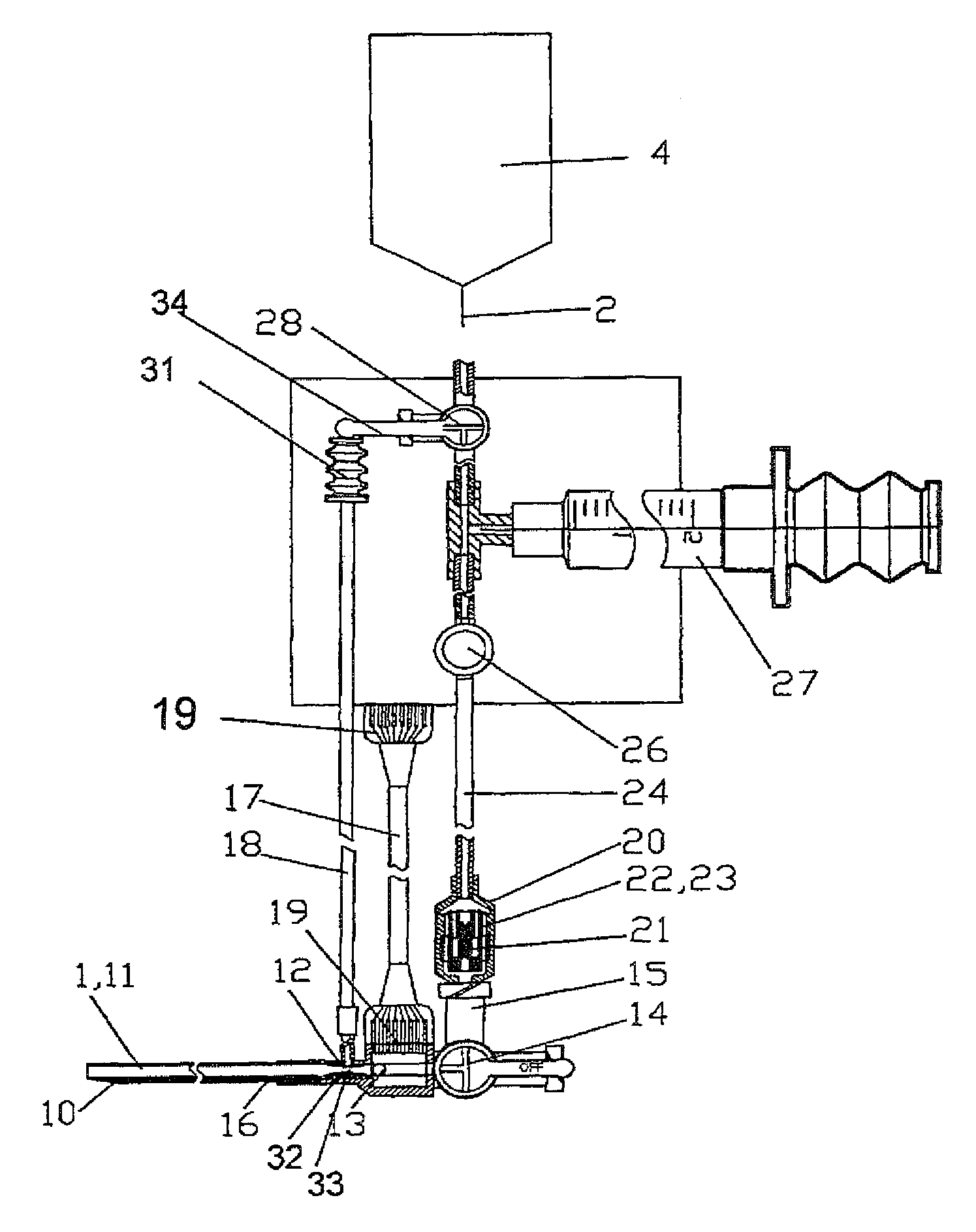
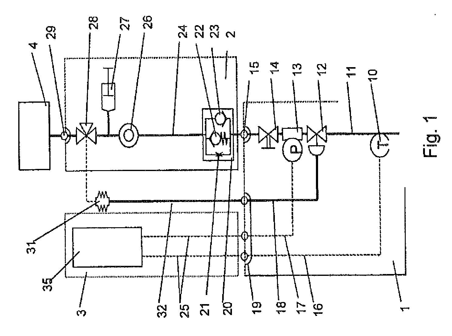
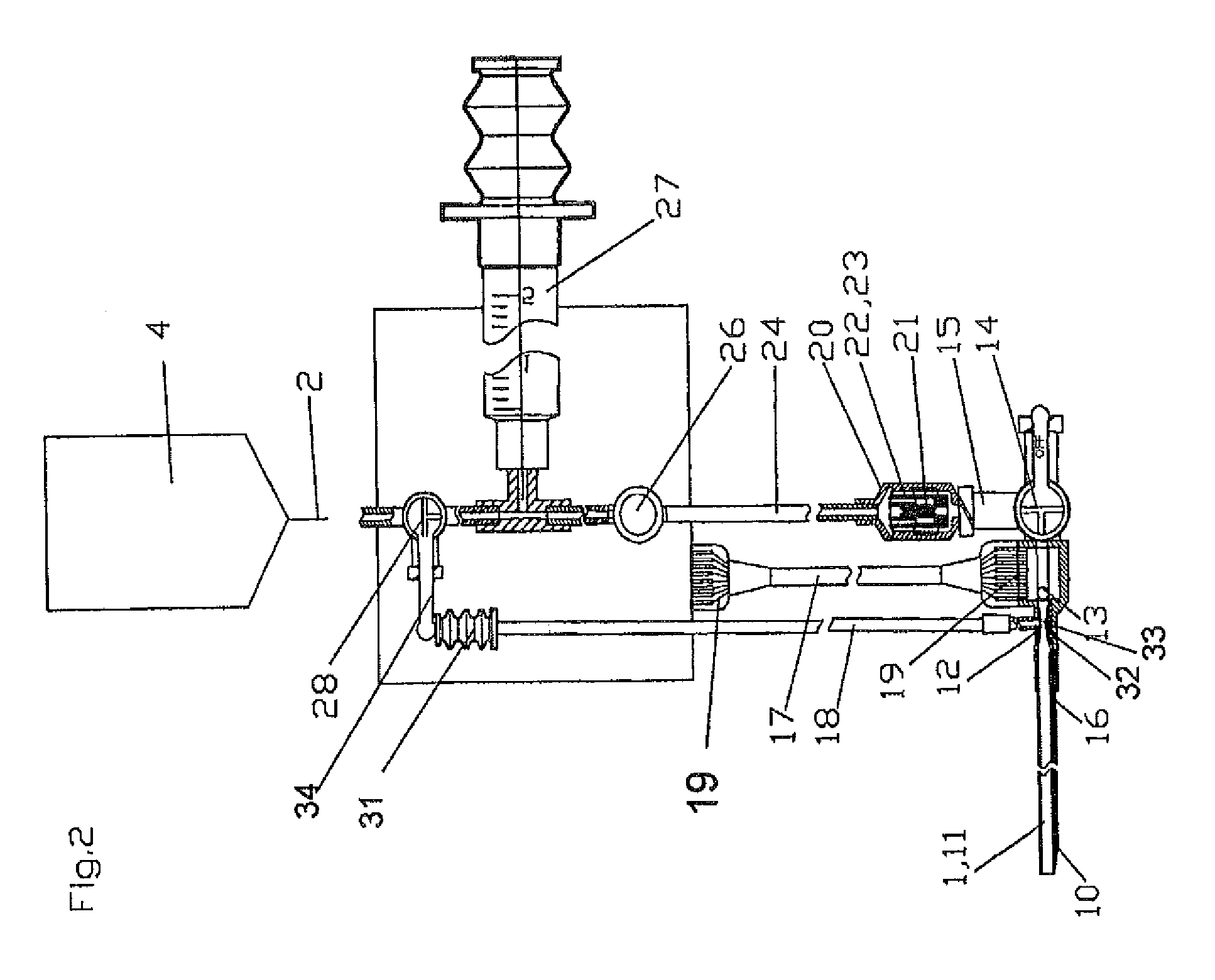
[0046]FIG. 1 shows a schematic view of a fluid transfer system for supplying an injected fluid into a patient's body. The fluid transfer system includes a blood vessel catheter unit 1, a fluid transfer unit 2, an operational unit 3, and a reservoir 4 for supplying a rinsing fluid. The blood vessel catheter unit 1 and the fluid transfer unit 2 may be coupled by a first interface 15 and the blood vessel catheter unit and the operational unit 3 are coupled by a second interface 19. Furthermore, the fluid transfer unit 2 may include a third interface 29 for coupling with the reservoir 4.

[0047]The blood vessel catheter unit 1 includes a catheter tube 11 having a tip end for penetrating a blood vessel of the patient's body. At another end of the catheter tube 11 a control valve 12 is arranged to cut off the flow of the injected fluid through the catheter tube 11 depending on an activation signal. The activation signal can be applied as a pneumatic, hydraulic or electrical signal. In the i...


PUM


Abstract

An injection system for injecting an injectate fluid into a blood vessel of the patient and for carrying out a blood pressure measurement of a patient. The injection system includes a catheter tube having a first end for penetrating the blood vessel of the patient, and a pressure sensor which is arranged close to a second end of the catheter tube and can sense a pressure of a liquid in the catheter tube as an indication of the blood pressure of the patient.

Description

[0001]The present application is a continuation of U.S. patent application Ser. No. 11 / 637,546, filed Dec. 12, 2006 entitled Blood Vessel Catheter and Injection System for Carrying Out a Blood Pressure Measurement of a Patient. It also claims priority to German application DE 10 200S 060079.4, filed Dec. 15, 2005, entitled Blood Vessel Catheter and Injection System for Carrying Out a Blood Pressure Measurement of a Patient. The entire disclosures of which are incorporated by reference herein.[0002]The present invention relates to blood vessel catheter located proximate to a patient's body for measuring blood pressure, drawing blood samples or injecting fluids into a blood vessel of the patient. The present invention further relates to a system for drawing blood samples or injecting fluids into the blood vessel of the patient and for carrying out a blood pressure measurement of a patient.BACKGROUND[0003]Measurement systems for measuring blood pressure of a patient's body are well kno...

Claims


Application Information

Patent Timeline
Patent Type & Authority Applications(United States)
IPC IPC(8): A61B5/0215
CPCA61B5/0215A61M5/14A61M25/0097A61M2205/3344A61M2005/1403A61M2039/0205A61M39/22
Inventor PFEIFFER, ULRICHMOULAS, DANIELKNOLL, REINHOLD
Owner EDWARDS LIFESCIENCES IPRM AG
Learn More