
Injection molded cover element with uninterrupted hole pattern

a technology of injection molding and pattern, which is applied in the direction of roofs, transportation and packaging, transducer casings/cabinets/supports, etc., can solve the problems of undesired appearance, inability to produce a truncated hole, and imposed limits on the hole, so as to improve the appearance and therefore processing quality, reduce the depth of the finished blind hole, and reduce the diameter

Inactive Publication Date: 2013-01-03
FORD GLOBAL TECH LLC
View PDF11 Cites 31 Cited by
  • Summary
  • Abstract
  • Description
  • Claims
  • Application Information

AI Technical Summary

Benefits of technology

The invention relates to a method for reducing the depth of blind holes in a cover element or loudspeaker grille, resulting in a more uniform appearance and no small segments being perceived. The geometrical order of the hole pattern is not changed, allowing for creative freedom and integration with the surrounding environment. The cover element can have any imaginable hole pattern, including round, angular, or hexagonal, and the method can be used for covering all possible openings. The cover element is manufactured from plastics material using an injection molding process, with the end edge region having pins that are maintained and not destroyed during the process. These technical effects improve the appearance and processing quality of the loudspeaker.

Problems solved by technology

At the edge of the pattern, however, the holes are subject to limits imposed by the production process.
It is typically not possible to produce a truncated hole with a hole size less than half the diameter of a hole.
A frayed, imperfect, undesired appearance is produced by the omission of this grille pattern in this edge region.
The creation of such geometries involves great effort and may take up to four days or more for a designer to develop, depending on the design and grille size, if each hole has to be created individually.
For a speaker grille, all of these additional efforts to develop modified hole patterns may have an undesirable affect on the acoustic properties.
This geometry does not allow any change or adjustment of the holes by different sizes and distances.

Method used


Image

  • Injection molded cover element with uninterrupted hole pattern
  • Injection molded cover element with uninterrupted hole pattern
  • Injection molded cover element with uninterrupted hole pattern

Examples


Embodiment Construction

[0027]In the different figures, like parts are always denoted by like reference signs and are therefore generally also only described once.

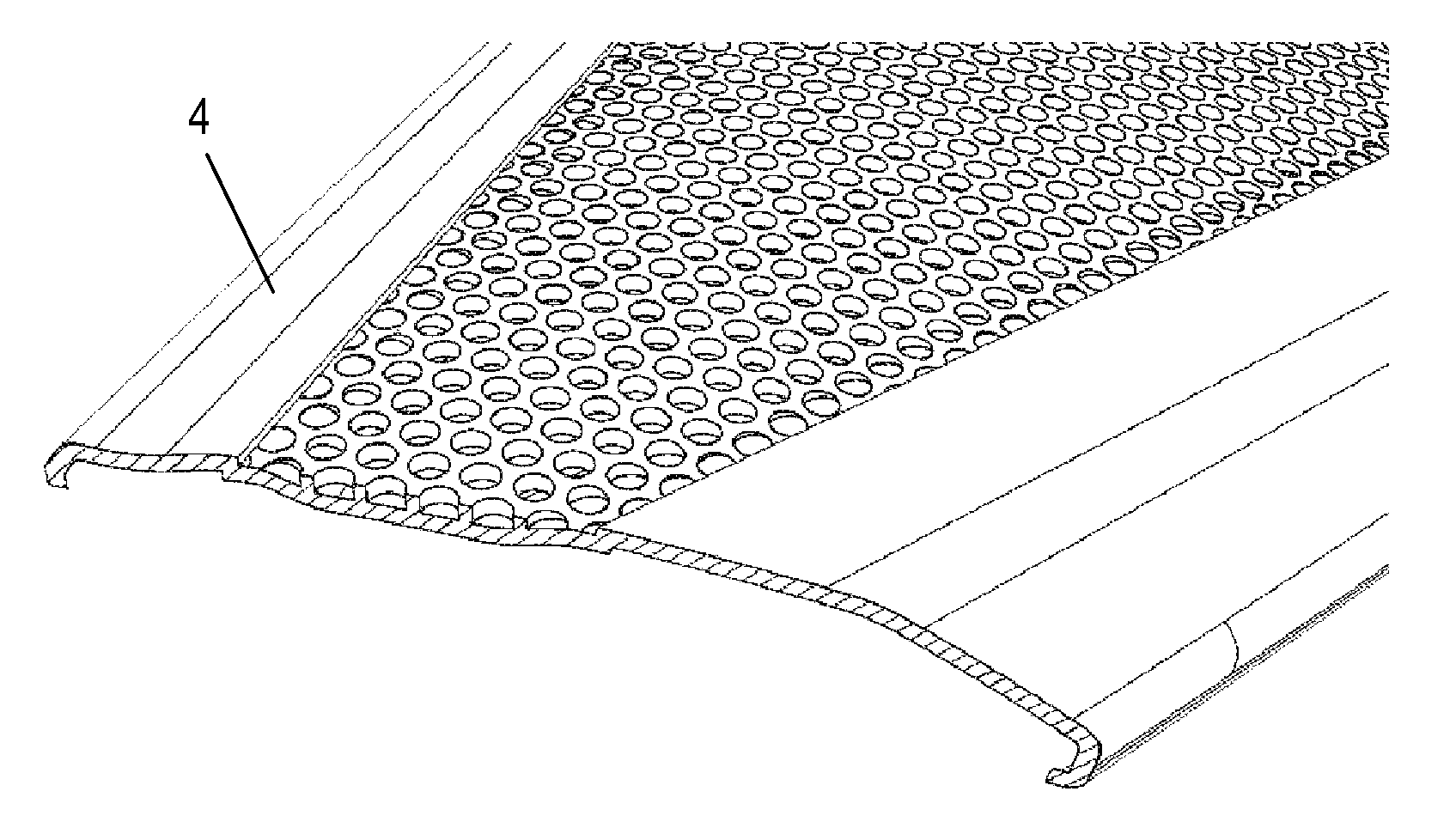
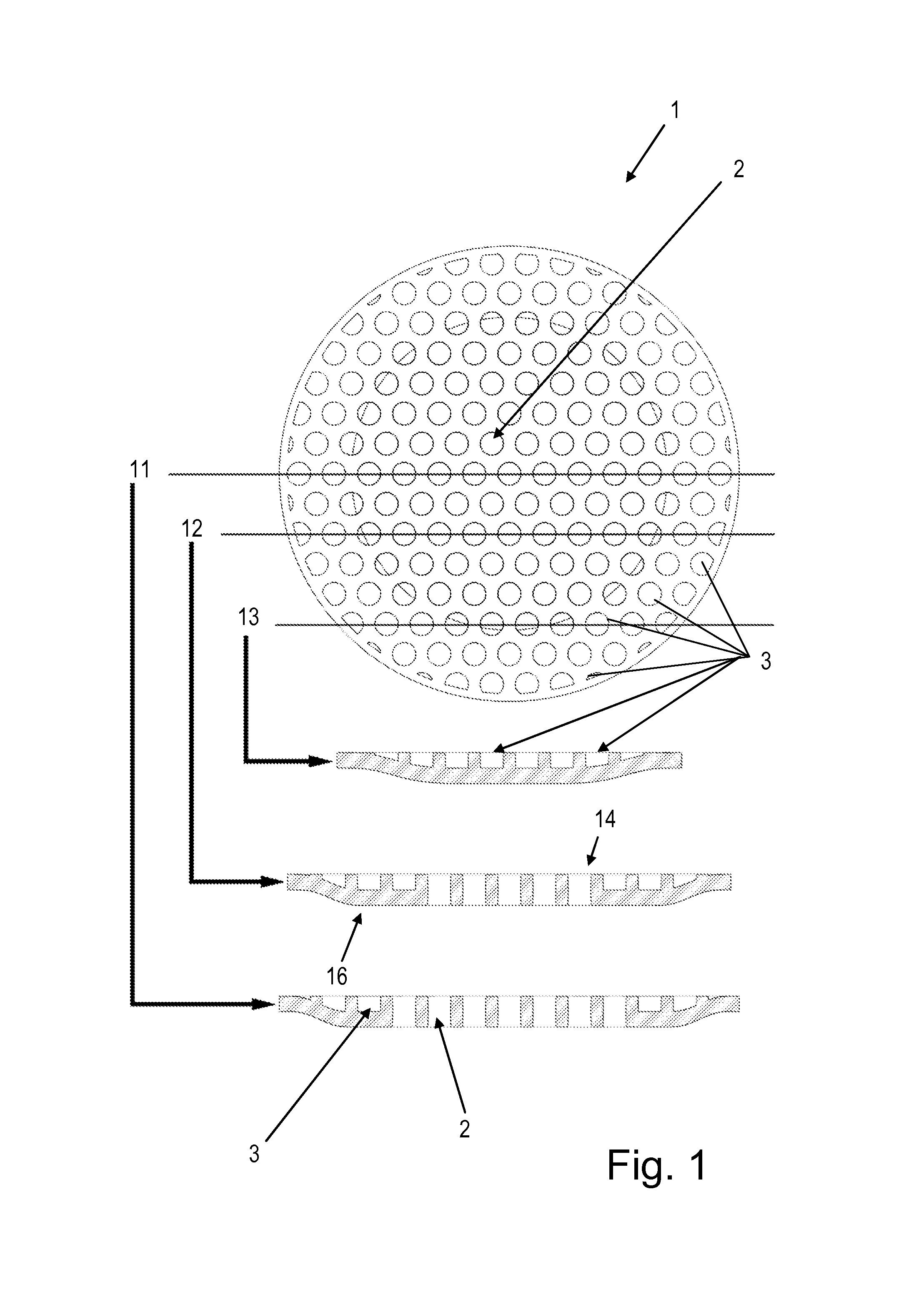
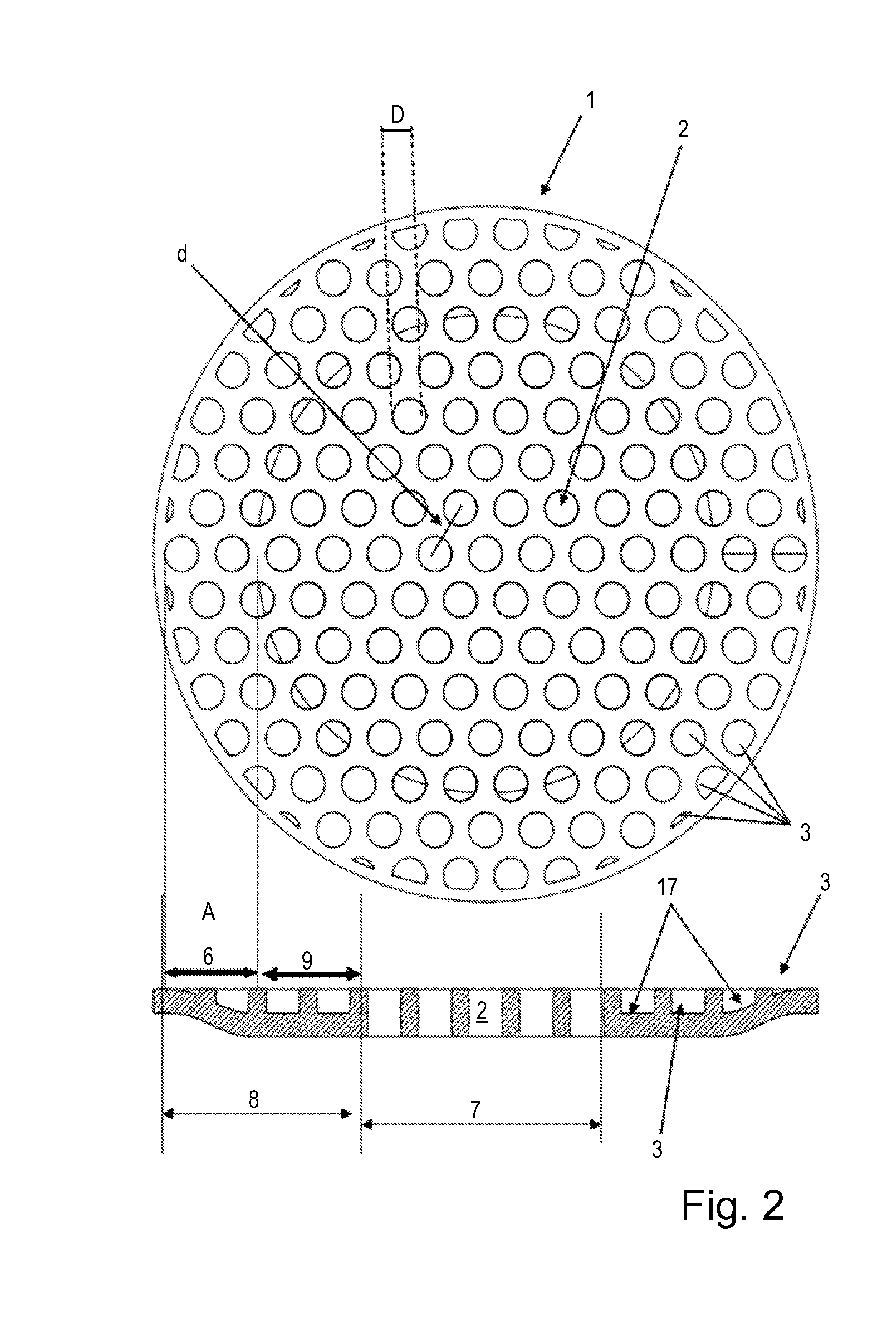
[0028]FIG. 1 shows a cover element 1 or a grille element 1, which has through-holes 2 and blind holes 3 as well as a hole-free rim 4 (FIGS. 3 and 4), the cover element 1 being produced from a plastics material by injection molding. The blind holes 3 occupy an edge region 8 which may include an end edge subregion 6 (FIG. 2) wherein the depth of blind holes 3 is generally decreasing in proportion to the proximity of holes 3 to rim 4.

[0029]In the exemplary embodiment illustrated in FIG. 1, the cover element 1 is designed by way of example as a loudspeaker grille 1. The cover element 1 has an acoustically active zone 7 (with through holes 2) and an acoustically passive zone 8 (with blind holes 3).

[0030]The acoustically passive zone 8 can thus also be referred to as an edge region 8, which has two subregions: an inter-edge region 9 and the end edge re...


PUM


Abstract

A plastic molded trim panel for a vehicle provides a cover element formed as an injection-molded panel with a visible side and an underside. The cover element has a smooth outer rim region, a patterned central region, and an edge region between them. The patterned central region includes a first plurality of regularly-spaced holes disposed in the visible side with a predetermined pattern and having a first substantially uniform depth. The edge region includes a second plurality of regularly-spaced holes disposed in the visible side uniformly continuing the predetermined pattern and having a generally decreasing depth according to proximity to the rim region. The rim region is smooth on the visible side without holes. The decreasing depth of the holes allows an uninterrupted hole pattern to be used because the truncated holes at the edge of the pattern remain to be manufacturable using injection molding.

Description

CROSS REFERENCE TO RELATED APPLICATIONS[0001]Not Applicable.STATEMENT REGARDING FEDERALLY SPONSORED RESEARCH[0002]Not Applicable.BACKGROUND OF THE INVENTION[0003]The present invention relates to a cover element having through-holes and blind holes as well as a hole-free rim, wherein the cover element is produced from a plastics material by injection molding.[0004]Cover elements or grille elements of this type are known in the automotive industry and, for example, can cover recesses or openings in vehicle doors, in the dashboard, or in other motor vehicle elements. For example, air ventilation outlets or loudspeakers can be covered. When creating grille structures having geometrical hole patterns, if the cover edges are trimmed or shaped in a manner deviating from the geometrical arrangement, there occur regions of different sizes in which truncated holes would be created having a size that is below what can be obtained by the production process. Consequently, the truncated holes are...

Claims


Application Information

Patent Timeline
Patent Type & Authority Applications(United States)
IPC IPC(8): B60R13/02
CPCB60R13/02H04R2499/15H04R1/023B60R11/0217H04R2499/13
Inventor STEIN, JOERG
Owner FORD GLOBAL TECH LLC
Learn More