
Transformer and display device using the same

a technology of display device and transformer, applied in the field of transformer, can solve the problems of difficult design of switching transformer, difficult to meet safety standards, etc., and achieve the effect of reducing leakage inductan

Active Publication Date: 2013-01-03
SOLUM CO LTD
View PDF2 Cites 13 Cited by
  • Summary
  • Abstract
  • Description
  • Claims
  • Application Information

AI Technical Summary

Benefits of technology

The patent text describes a transformer that can reduce leakage inductance. This means that the transformer can minimize the negative effects of a magnetic field on other components in a circuit. This can improve the performance and reliability of the transformer.

Problems solved by technology

However, in accordance with the miniaturization of the switching transformer, it is not easy to design a switching transformer having small leakage inductance.
In addition, in the case in which a small-sized transformer, as described above, is manufactured, since a primary coil and a secondary coil are disposed to be immediately adjacent to each other, it may be difficult to satisfy safety standards (that is, those of Underwriters Laboratories (UL)) due to the arrangement thereof.

Method used


Image

  • Transformer and display device using the same
  • Transformer and display device using the same
  • Transformer and display device using the same

Examples


Embodiment Construction

[0045]The terms and words used in the present specification and claims should not be interpreted as being limited to typical meanings or dictionary definitions, but should be interpreted as having meanings and concepts relevant to the technical scope of the present invention based on the rule according to which an inventor can appropriately define the concept of the term to appropriately describe the method he or she knows for carrying out the invention. Therefore, the configurations described in the embodiments and drawings of the present invention are merely the embodiments, but do not represent all of the technical spirit of the present invention. Thus, the present invention should be construed as including all the changes, equivalents, and substitutions included in the spirit and scope of the present invention at the time of the filing of this application.

[0046]Hereinafter, embodiments of the present invention will be described in detail with reference to the accompanying drawin...


PUM

PropertyMeasurementUnit
angleaaaaaaaaaa
angleaaaaaaaaaa
outer diameteraaaaaaaaaa

Abstract

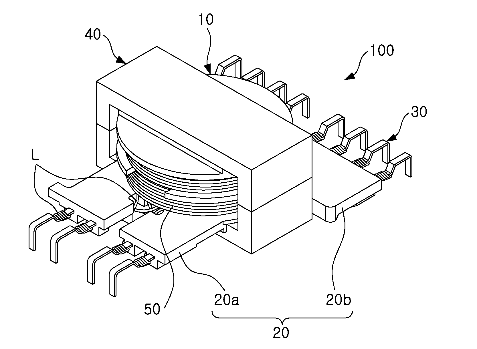
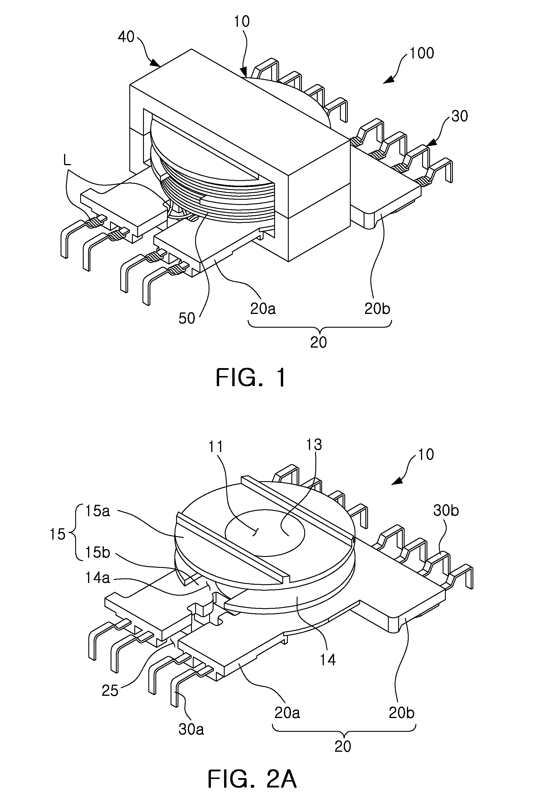
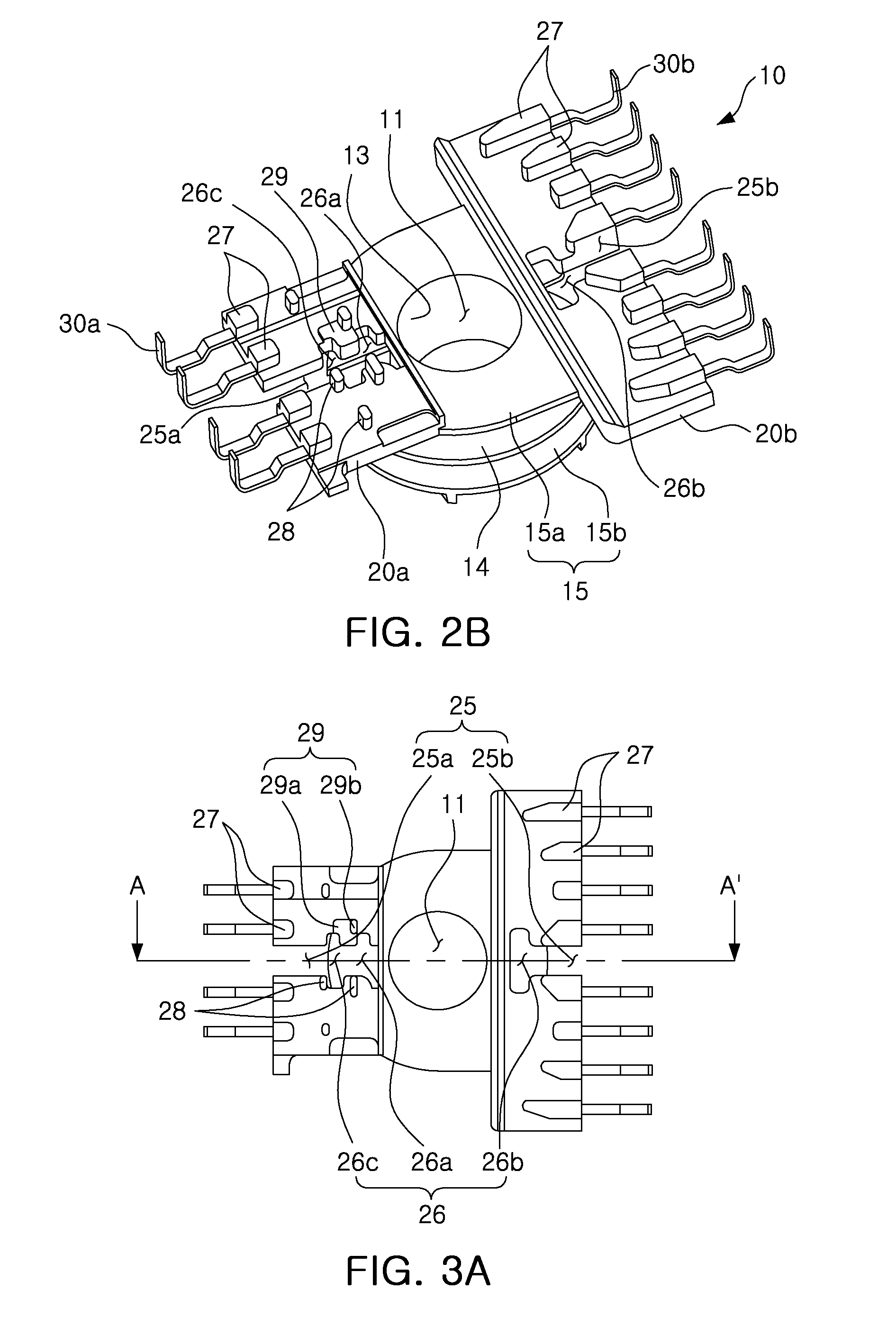
There is provided a transformer capable of significantly reducing leakage inductance while satisfying safety standards. The transformer includes: a winding part having a plurality of coils wound on an outer peripheral surface of a pipe shaped body part while being stacked thereon; and a terminal connection part extended from one end of the winding part in an outer diameter direction thereof and having a plurality of external connection terminals coupled to a distal end thereof, the terminal connection part including at least one catching groove formed such that the coils are led to the outside of the winding part therethrough, and a lead wire of at least one of the coils being led to the outside of the winding part while maintaining a winding direction of the coils.

Description

CROSS-REFERENCE TO RELATED APPLICATIONS[0001]This application claims the priority of Korean Patent Application No. 10-2011-0065120 filed on Jun. 30, 2011, in the Korean Intellectual Property Office, the disclosure of which is incorporated herein by reference.BACKGROUND OF THE INVENTION[0002]1. Field of the Invention[0003]The present invention relates to a transformer, and more particularly, to a transformer capable of significantly reducing leakage inductance while satisfying safety standards.[0004]2. Description of the Related Art[0005]Various kinds of power supplies are required in various electronic devices such as a television (TV), a monitor, a personal computer (PC), an office automation (OA) device, and the like. Therefore, these electronic devices generally include power supplies converting alternating current (AC) power supplied from the outside into power having an appropriate level for individual electronic appliances.[0006]Among power supplies, a power supply using a swi...

Claims


Application Information

Patent Timeline
Patent Type & Authority Applications(United States)
IPC IPC(8): H01F27/29
CPCH01F27/325H01F2005/043H01F2005/022G09G2330/06H01F27/2828G09G3/20H01F27/29H01F27/28G09G3/36
Inventor PARK, GEUN YOUNGLEE, YOUNG MINWON, JAE SUNKIM, JONG HAEKIM, DEUK HOON
Owner SOLUM CO LTD
Learn More