
Dynamic Spectral Radiance Calibration Source

Inactive Publication Date: 2013-01-03
GOVERNMENT OF THE UNITED STATES OF AMERICA AS REPRESENTED BY THE SEC OF COMMERCE THE NAT INST OF STANDARDS & TEHCNOLOGY
View PDF3 Cites 37 Cited by
  • Summary
  • Abstract
  • Description
  • Claims
  • Application Information

AI Technical Summary

Benefits of technology

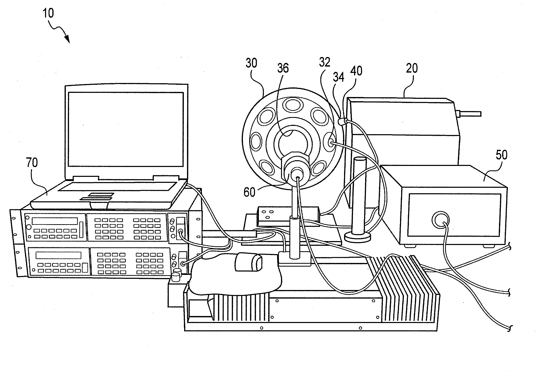
The present invention provides a system and method for a dynamic spectral radiance calibration source. The system includes an integrating sphere, a user defineable light source, an unfiltered detector, and a reference spectrometer. The method involves adjusting the light output of the light source to match the observed spectra of the reference spectrometer. The system and method can be used to measure and produce specific radiance spectra. The technical effects include improved accuracy and efficiency in spectral calibration and the ability to measure and produce desired radiance spectra.

Problems solved by technology

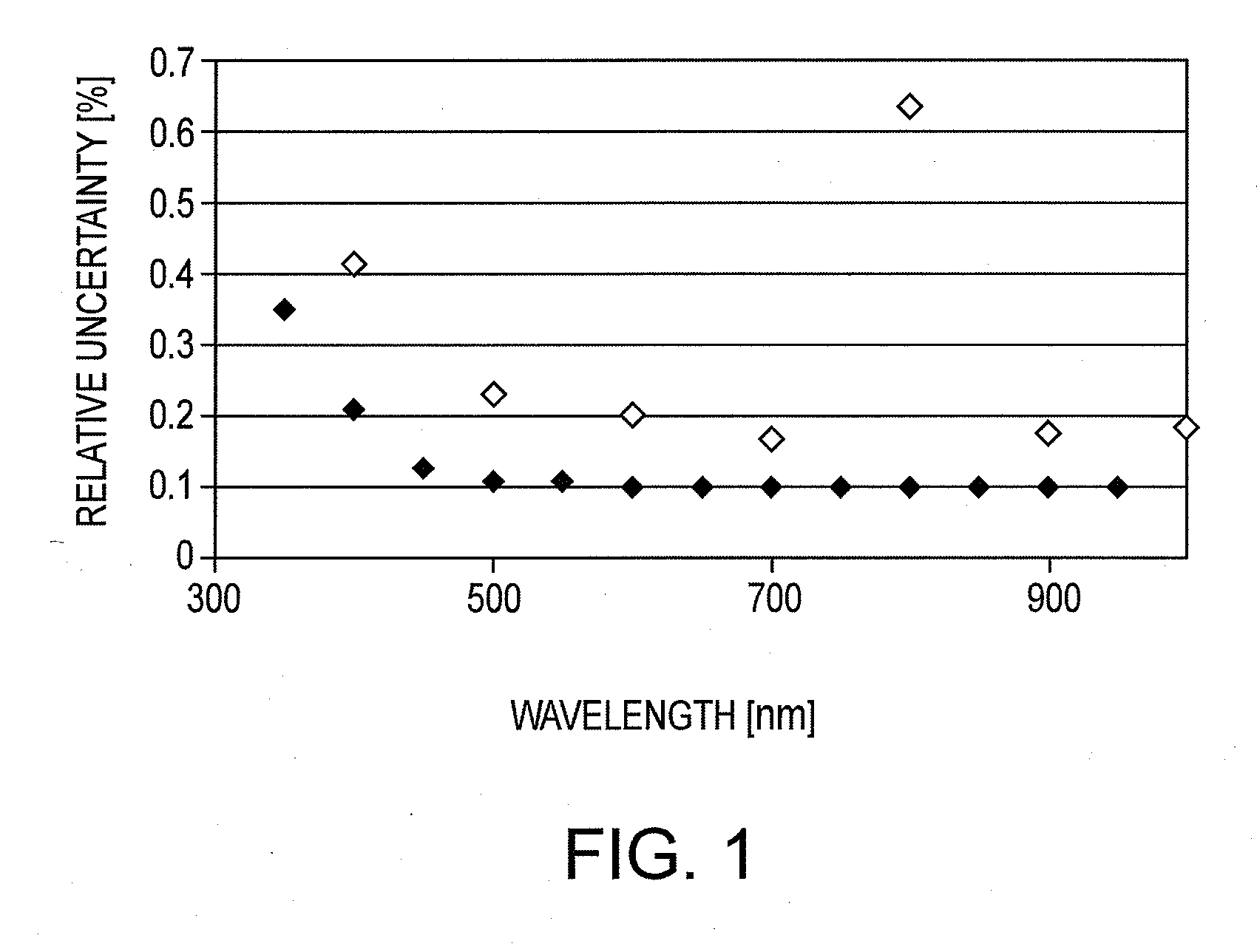
However, it is significantly lower than the uncertainty in the disseminated scale determined by NASA's Earth Observing System's validation campaign.

Method used


Image

  • Dynamic Spectral Radiance Calibration Source
  • Dynamic Spectral Radiance Calibration Source
  • Dynamic Spectral Radiance Calibration Source

Examples


example 1

Oximetric Imaging of Human Tissue

[0083]A preferred embodiment system can be used for characterizing and / or providing a chemometric scale for oxyhemoglobin (HbO2). The sensor under test would illuminate the integrating sphere, in place of human tissue, use the spectral distribution of the illumination source convolved with a known spectral reflectance signature for a given HbO2 tissue concentration and output a corresponding spectral radiance, as an equivalent to the reflected light from human tissue. A series of such steps can be repeated with variable HbO2 concentrations to provide a chemometric scale. This allows a reproducible substitution of the tissue with a known spectral radiance level. The substitution of the tissue with the preferred embodiment system can be referred to as a Digital Tissue Phantom.

example 2

Epifluorescence Microscope Characterization

[0084]An epifluorescence microscope would have the integrating sphere (or equivalent) inserted where the microscope slide would be mounted. The excitation source from the microscope would be measured for intensity and spectral distribution. The measured source spectral distribution is used to produce a corresponding emission spectrum for a given substance, i.e. green fluorescent protein. The output emission spectrum can either be static or change as a function of time in order to mimic a decaying emission. The preferred embodiment system, in this application, substitutes either a slide specimen or a physical calibration artifact.

example 3

Ocean Color Sensor Characterization

[0085]A sensor used to measure the ocean color (or any spectral sensor ranging from a portable spectrometer to a satellite sensor) can be considered as a sensor under test. The preferred embodiment system would be used to measure the solar spectral irradiance. The measured solar spectral irradiance would be used with a known chlorophyll concentration representative of an open body of water to produce a corresponding water leaving radiance as the output of the preferred embodiment system. This process can be repeated for various chlorophyll concentrations in order to validate the range of the sensor under test.

[0086]The preferred embodiment system is an absolutely calibrated, spectrally tunable detector based source of spectral radiance. A detector based radiance scale is simpler to maintain and offers the possibility of reduced uncertainties in the spectral radiance of the integrating sphere sources with broad spectral distributions over convention...


PUM


Abstract

Systems and methods for measuring spectral distribution of an illumination source and providing desired output spectral radiance are described. The systems include a user defineable light source, an integrating sphere, and one or more light detectors.

Description

CROSS REFERENCES TO RELATED APPLICATIONS[0001]This application claims priority from U.S. provisional application Ser. No. 61 / 429,213 filed on Jan. 3, 2011.STATEMENT AS TO RIGHTS TO INVENTION(S) MADE UNDER FEDERALLY-SPONSORED RESEARCH AND DEVELOPMENT[0002]The US Government, through the National Institute of Standards and Testing, is the owner of this invention.FIELD[0003]The present invention relates to systems and related methods for measuring spectral distribution of an illumination source and / or illuminated samples. The present invention also relates to systems and methods for providing a desired spectral radiance output.BACKGROUND[0004]There are currently two dominant approaches to calibrating instruments for radiance responsivity. A first approach utilizes broadband sources, commonly known as lamp illuminated integrating sphere sources (ISSs) or lamp illuminated plaques with a source radiant flux traceable to primary melting and freezing point blackbodies. A second approach uses...

Claims


Application Information

Patent Timeline
Patent Type & Authority Applications(United States)
IPC IPC(8): G01J1/32G01J3/28G01J3/443G01J1/42
CPCG01J3/28G01J3/0254G01J3/021G01J3/0297G01N2201/0632G01J3/18G01N21/274G01J3/0218G01J3/0229G01J3/10
Inventor ALLEN, DAVID W.BROWN, STEVEN W.LITORJA, MARITONI
Owner GOVERNMENT OF THE UNITED STATES OF AMERICA AS REPRESENTED BY THE SEC OF COMMERCE THE NAT INST OF STANDARDS & TEHCNOLOGY
Learn More