

Electronic Safety Device
- Summary
- Abstract
- Description
- Claims
- Application Information
AI Technical Summary
Benefits of technology
Problems solved by technology
Method used
Image

Examples
Embodiment Construction
[0033]In the majority of automation systems, DC voltages are used for supplying a plant control system and its peripherals. A global 24 V DC voltage standard has been established and employed for many years. This voltage is available as a control voltage. In many plants this control voltage can also be a 230 V AC voltage or any other voltage. In this case, the frequency of an AC voltage can be determined for specific plants. The invention relates to a wide variety of different supply systems, but in particular to safety devices for DC voltage systems, because these occur most frequently.
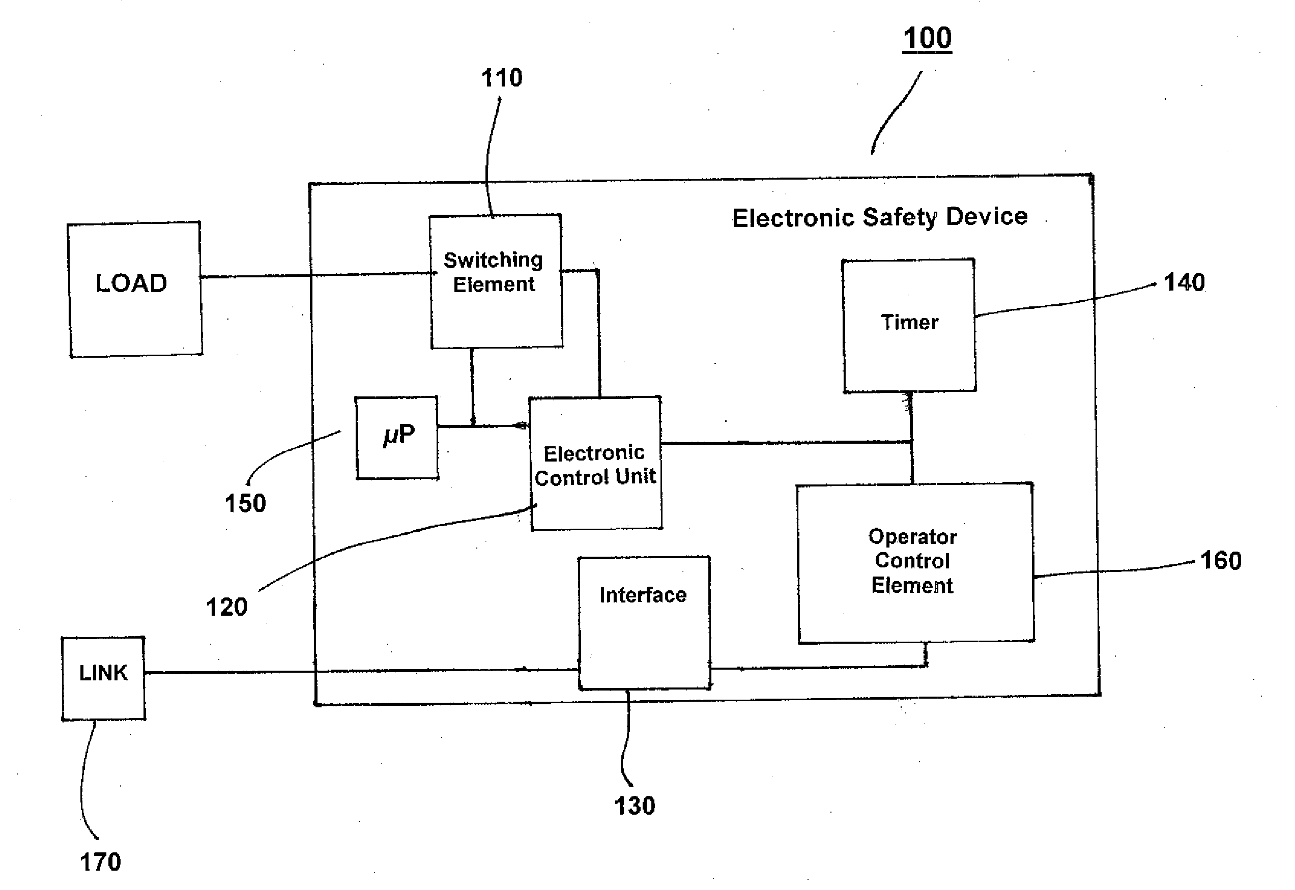
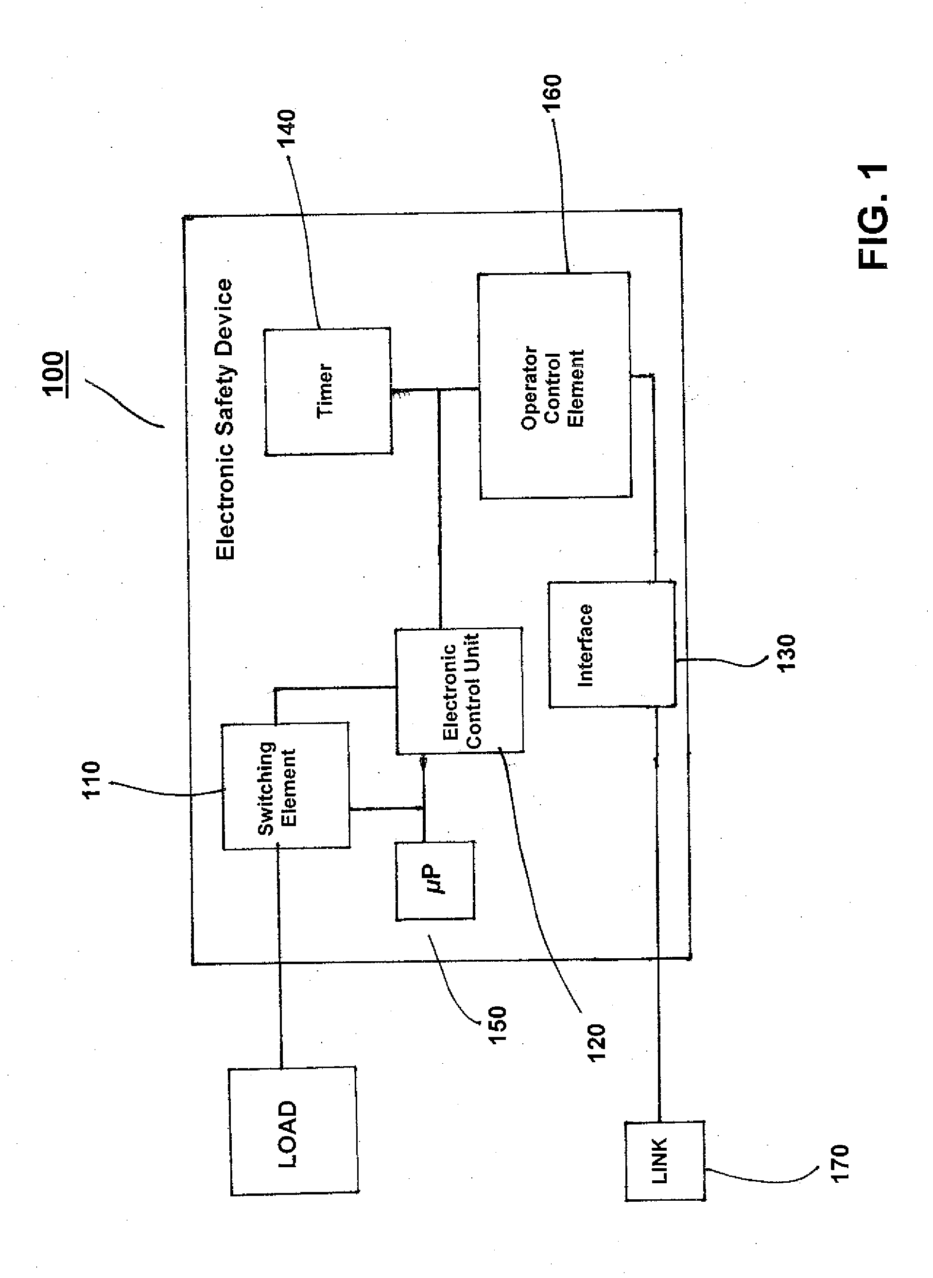
[0034]FIG. 1 is a schematic block diagram of the electronic safety device in accordance with the invention. The electronic safety device 100 includes an a switching element 110 and an electronic control unit 120, where a remote control interface 130 is provided for receiving control commands for the switching element 100, where it is possible for the electronic control unit 120 to trigger the switchi...
PUM
 Abstract
Description
Claims
Application Information