
Signal transmission method and signal receiving method in a multi-input multi-output system

a signal receiving and signal transmission technology, applied in the field of signal transmission methods in multi-input multi-output systems, can solve problems such as increased pilot overhead

Inactive Publication Date: 2011-09-08
LG ELECTRONICS INC
View PDF10 Cites 30 Cited by
  • Summary
  • Abstract
  • Description
  • Claims
  • Application Information

AI Technical Summary

Benefits of technology

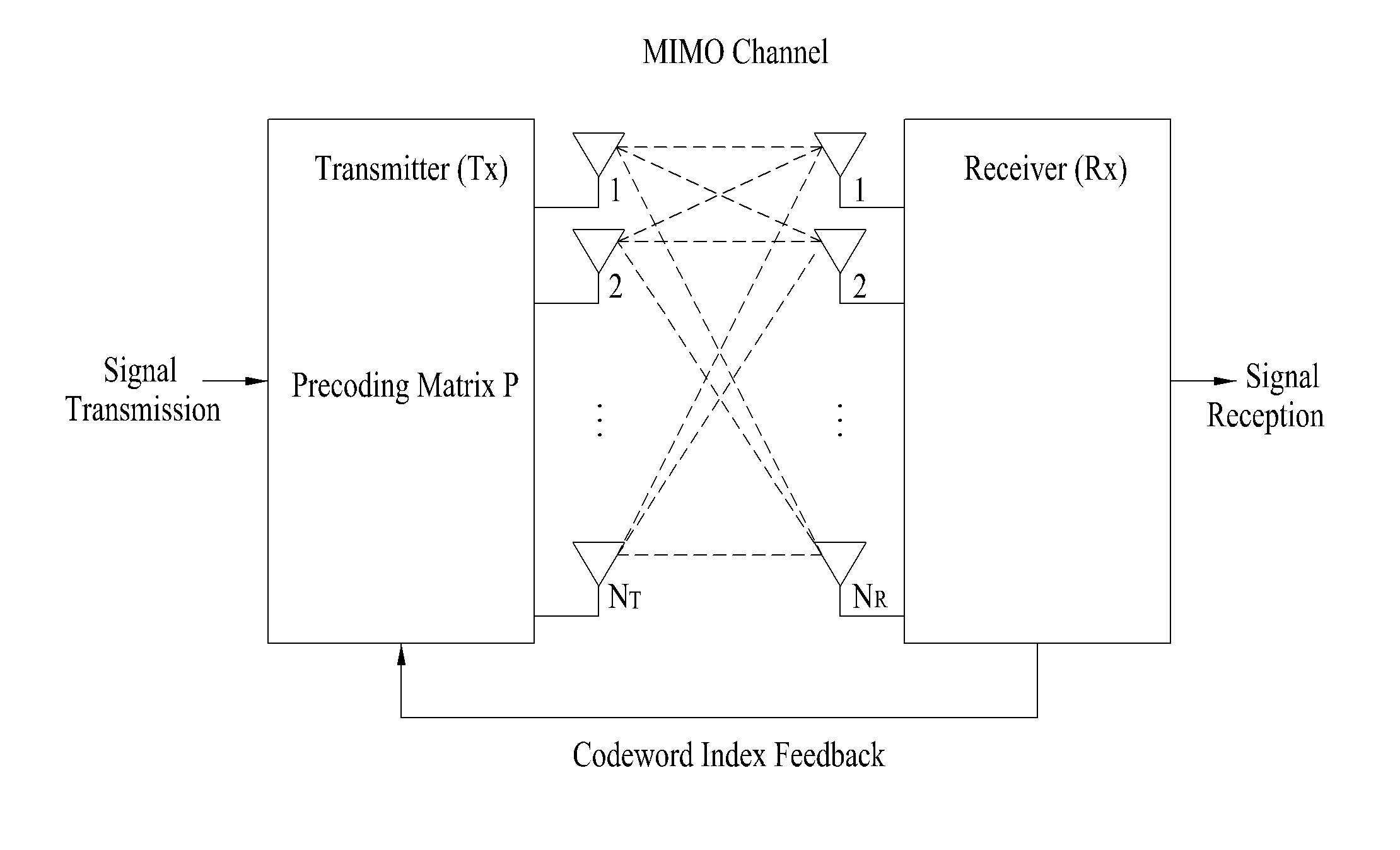
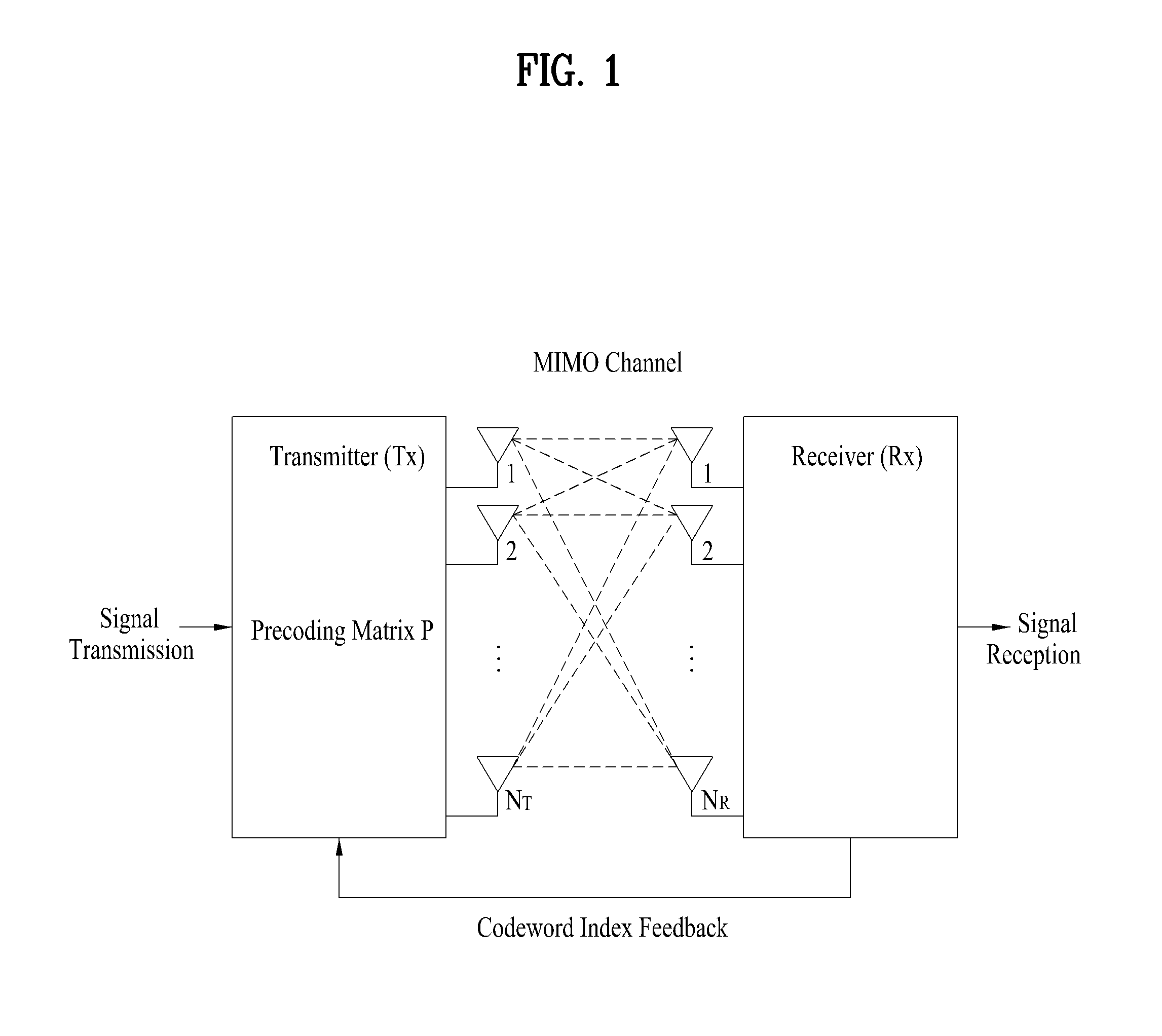
[0030]According to the above aspects of the present invention, if a nested structure in which a precoding matrix for a less number of streams is included in a precoding matrix for a greater number of streams is satisfied, it is convenient to calculate channel quality information or a plurality of users can share pilots.

Problems solved by technology

Generally, since a diversity scheme requires pilots for channel estimation corresponding to the number of antennas, it is problematic in that pilot overhead is increased.

Method used


Image

  • Signal transmission method and signal receiving method in a multi-input multi-output system
  • Signal transmission method and signal receiving method in a multi-input multi-output system
  • Signal transmission method and signal receiving method in a multi-input multi-output system

Examples


Embodiment Construction

[0035]Hereinafter, exemplary embodiments of the present invention will be described with reference to the accompanying drawings. It is to be understood that the detailed description, which will be disclosed along with the accompanying drawings, is intended to describe the exemplary embodiments of the present invention and is not intended to describe a unique embodiment through which the present invention can be carried out.

[0036]For instance, although a detailed example applied to a 3rd generation partnership project long term evolution (3GPP LTE) system is described hereinbelow, the present invention is applicable not only to the 3GPP LTE system but also to any wireless communication systems using a general multiple antenna system by the same principle. In the following description, the term base station may be replaced with other terms such as ‘Node B’, ‘eNode B’, etc., and the term terminal may be replaced with terms such as ‘user equipment (UE)’, ‘mobile station (MS)’, etc. A co...


PUM


Abstract

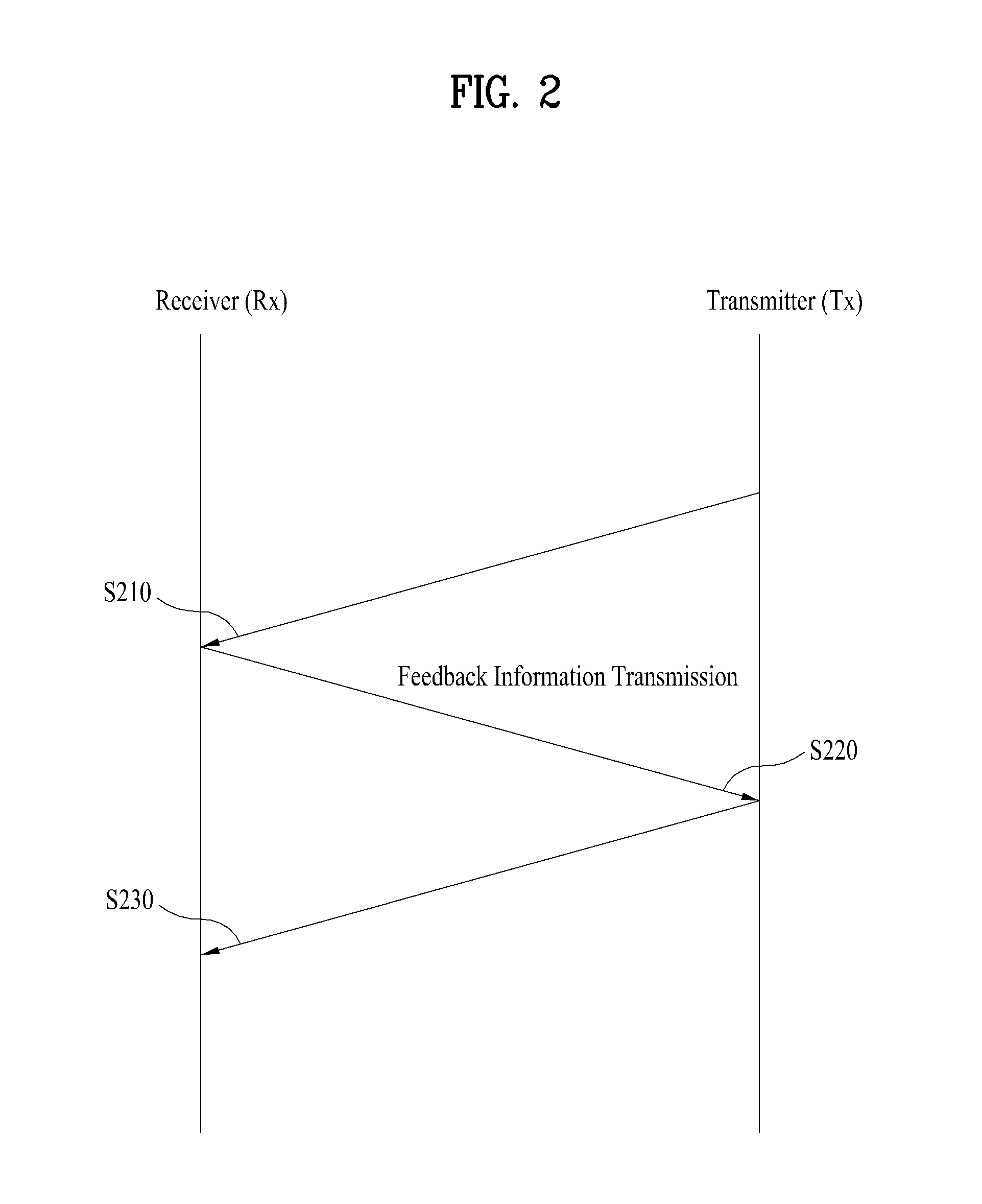
Disclosed is a signal transmission method comprising a feedback information receiving step of receiving a transmission rate and channel state information for transmission from a receiving end, a step of generating a signal to be transmitted by using a multi-antenna in accordance with the transmission rate, a step of performing a precoding on the generated signal by using the precoding matrix of the nested structure selected from a predetermined codebook in accordance with the transmission rate, and a step of transmitting the precoded signal. Said codebook includes a precoding matrix set in which a pre-coding matrix according to a first number of streams is not included in a precoding matrix according to a second number of streams greater than the first number of streams.

Description

TECHNICAL FIELD[0001]The following description relates to a signal transmission method in a multi-input multi-output (MIMO) system using a codebook which includes a precoding matrix set having a structure in which a precoding matrix according to a specific number of streams is included in a precoding matrix according to a greater number of streams and includes a precoding matrix set comprised of precoding matrices exhibiting optimal performance according to the number of streams although it does not have the above structure.BACKGROUND ART[0002]Recently, with the popularization of information communication services, the emergence of various multimedia services, and the provision of high-quality services, demand for high speed wireless communication services has rapidly increased. To actively cope with such demand, communication system capacity should be increased. To increase communication capacity in wireless communication environments, a method for searching new available frequency...

Claims


Application Information

Patent Timeline
Patent Type & Authority Applications(United States)
IPC IPC(8): H04L27/00
CPCH04B7/0434H04B7/0617H04B7/0478H04B7/063H04B7/0619H04B7/0482H04B7/0626
Inventor LEE, MOON ILLEE, WOOK BONGIHM, BIN CHULCHUN, JIN YOUNG
Owner LG ELECTRONICS INC
Learn More