System and methods for adaptive antenna optimization

a technology of adaptive antennas and optimization methods, applied in the field of antennas, can solve the problems of compromising efficiency, reducing the “electrical length” of the antenna, and increasing the difficulty of the antenna design

Active Publication Date: 2013-01-03
GOOGLE TECH HLDG LLC
View PDF7 Cites 90 Cited by
  • Summary
  • Abstract
  • Description
  • Claims
  • Application Information

AI Technical Summary

Problems solved by technology

As the devices continue to get smaller, the shrinking physical form factor makes antenna design more difficult.
The “electrical length” of the antenna becomes reduced, thereby compromising efficiency.
Further complicating matters are the demands to provide addit

Method used


Image

  • System and methods for adaptive antenna optimization
  • System and methods for adaptive antenna optimization
  • System and methods for adaptive antenna optimization

Examples


Embodiment Construction

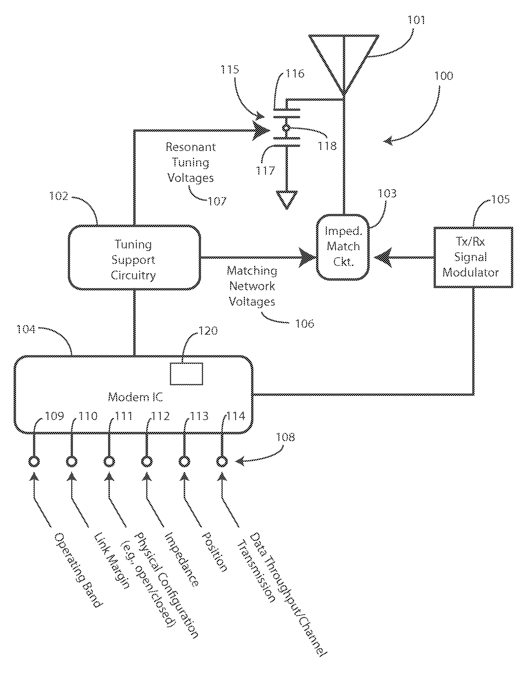
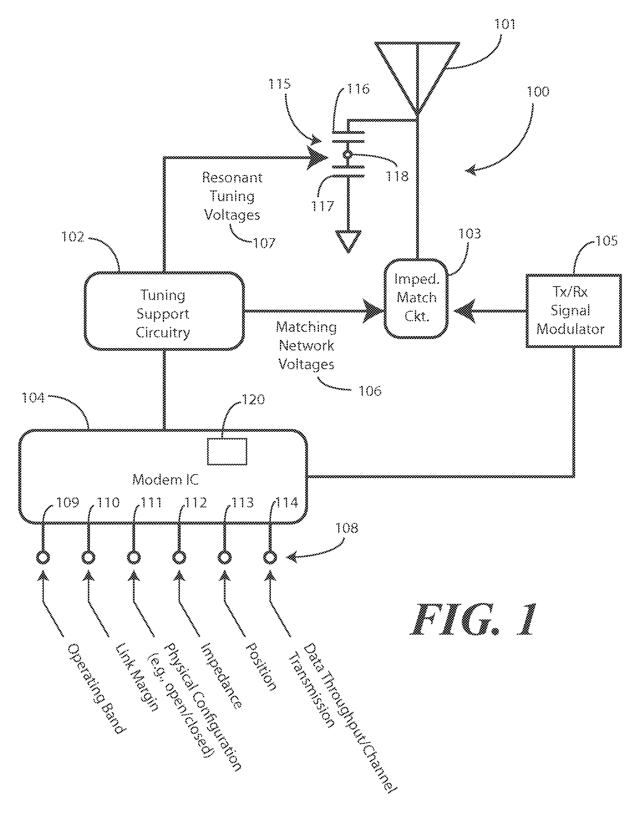
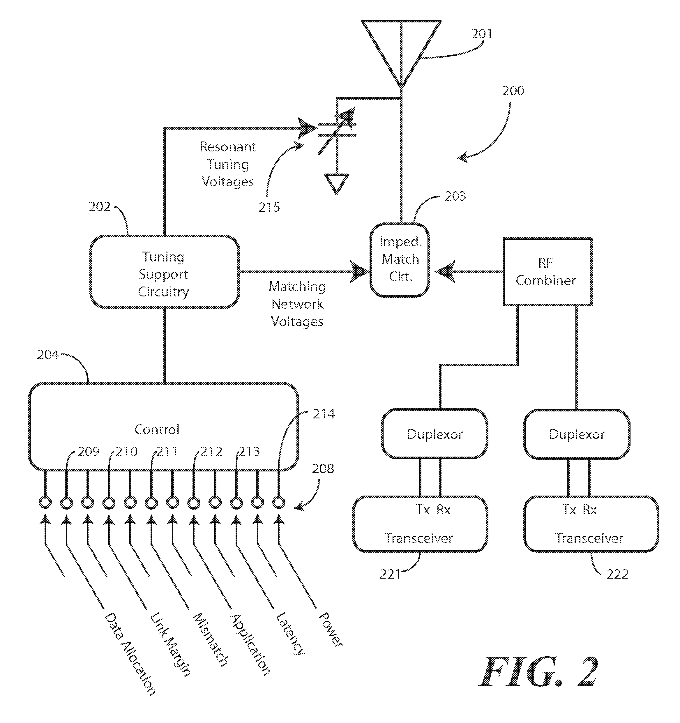
[0014]Before describing in detail embodiments that are in accordance with the present invention, it should be observed that the embodiments reside primarily in combinations of method steps and apparatus components related to improving the efficiency of an antenna operating in a wireless communication device. Any process descriptions or blocks in flow charts should be understood as representing modules, segments, or portions of code that include one or more executable instructions for implementing specific logical functions or steps in the process. Alternate implementations are included, and it will be clear that functions may be executed out of order from that shown or discussed, including substantially concurrently or in reverse order, depending on the functionality involved. Accordingly, the apparatus components and method steps have been represented where appropriate by conventional symbols in the drawings, showing only those specific details that are pertinent to understanding t...


PUM


Abstract

A method (600) and devices for enhancing the performance of one or more antennas (440) is provided. A control circuit (104) assesses performance of an antenna (101) in a plurality of bands, such as a receive band and a transmit band. The control circuit (104) then selects one of the bands, e.g., a lesser performing band, as a “selected band” for which the antenna (101) will be optimized. The control circuit (104) can then adjust an adjustable impedance matching circuit (103) coupled to the antenna (101) to improve the efficiency of the antenna (101) in the selected band and can adjust a resonance of the antenna (101) to further improve an efficiency of the antenna (101) in the selected band.

Description

BACKGROUND[0001]1. Technical Field[0002]This invention relates generally to antennas, and more particularly to antennas in wireless communication devices.[0003]2. Background Art[0004]Wireless communication devices, such as mobile telephones, smart phones, palm-top computers, or personal digital assistants, employ antennas for wireless communication. These antennas are frequently internal antennas embedded within the housing of the wireless communication device. As the devices continue to get smaller, the shrinking physical form factor makes antenna design more difficult. The “electrical length” of the antenna becomes reduced, thereby compromising efficiency. Further complicating matters are the demands to provide additional bandwidth support in one or more antennas disposed within such devices. Moreover, the antennas in these devices are required to function in a variety of conditions, such as with a user's hands placed in different locations, different physical orientations, and so...

Claims


Application Information

Patent Timeline
IPC IPC(8): H04W4/00
CPCH01Q1/2266H01Q1/242H01Q9/145H01Q21/28H01Q21/30
Inventor KLOMSDORF, ARMIN W.ALBERTH, WILLIAM P.BLACK, GREGORY R.MACH, RICHARD E.
Owner GOOGLE TECH HLDG LLC
Why Eureka
Try Eureka