
Automated Calibration Method and System for a Diagnostic Analyzer

a diagnostic analyzer and automatic calibration technology, applied in the field of diagnostic instruments, can solve the problems of difficult approach and high cost of market, and achieve the effect of accurately providing patient sample diagnostic results

Active Publication Date: 2013-01-03
IDEXX LABORATORIES
View PDF28 Cites 1 Cited by
  • Summary
  • Abstract
  • Description
  • Claims
  • Application Information

AI Technical Summary

Benefits of technology

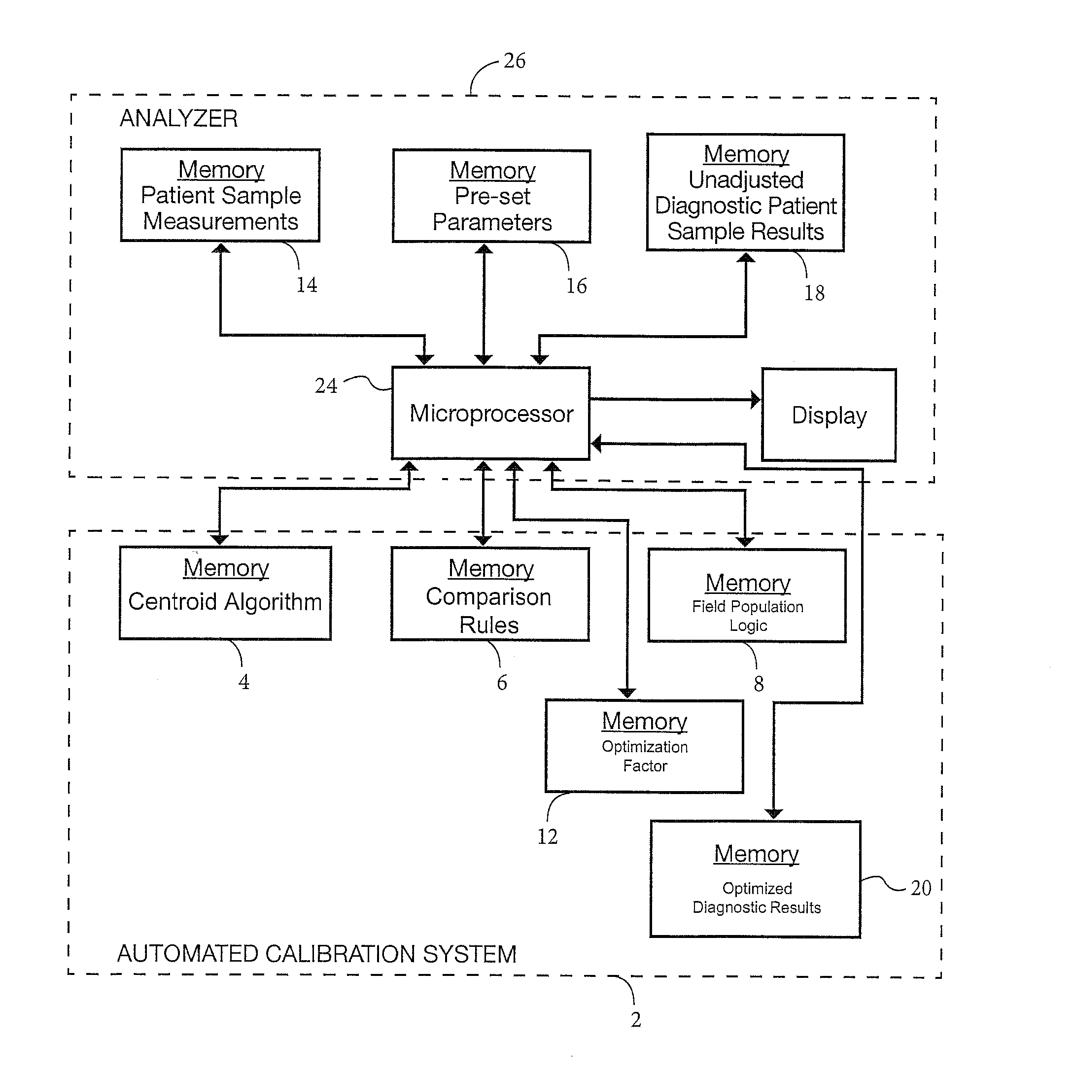
The present invention provides an automated system and method for calibrating a diagnostic analyzer that can overcome the limitations of known systems and methods. The method and system adjust the diagnostic results of patient samples by applying an optimization factor to the calculations performed by the analyzer. This optimization factor can modify the analyzer's pre-set parameters without actually changing them, resulting in more accurate patient sample diagnostic results. The optimized results represent a modified calculation of the patient sample diagnostic results. The optimization factor can be a multiplying factor or an offset factor. Overall, the technology improves the accuracy and reliability of diagnostic analyzer results.

Problems solved by technology

The veterinary market is very cost sensitive and controls are not run in the same manner as in human practices, which generally run fixed cell controls approximately at least once per 8-hour shift.
This approach can run into difficulties if there are external factors that cause system shifts, such as reagent lot changes.

Method used


Image

  • Automated Calibration Method and System for a Diagnostic Analyzer
  • Automated Calibration Method and System for a Diagnostic Analyzer
  • Automated Calibration Method and System for a Diagnostic Analyzer

Examples


Embodiment Construction

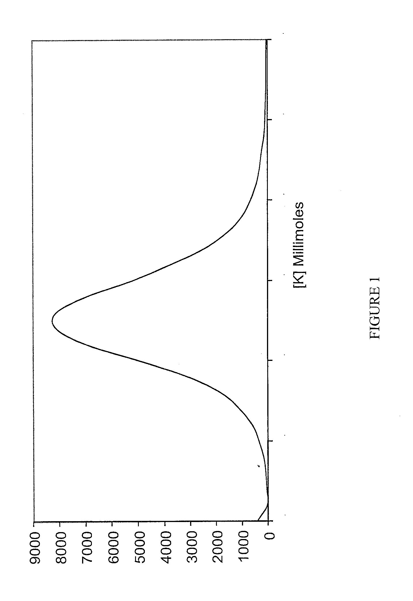
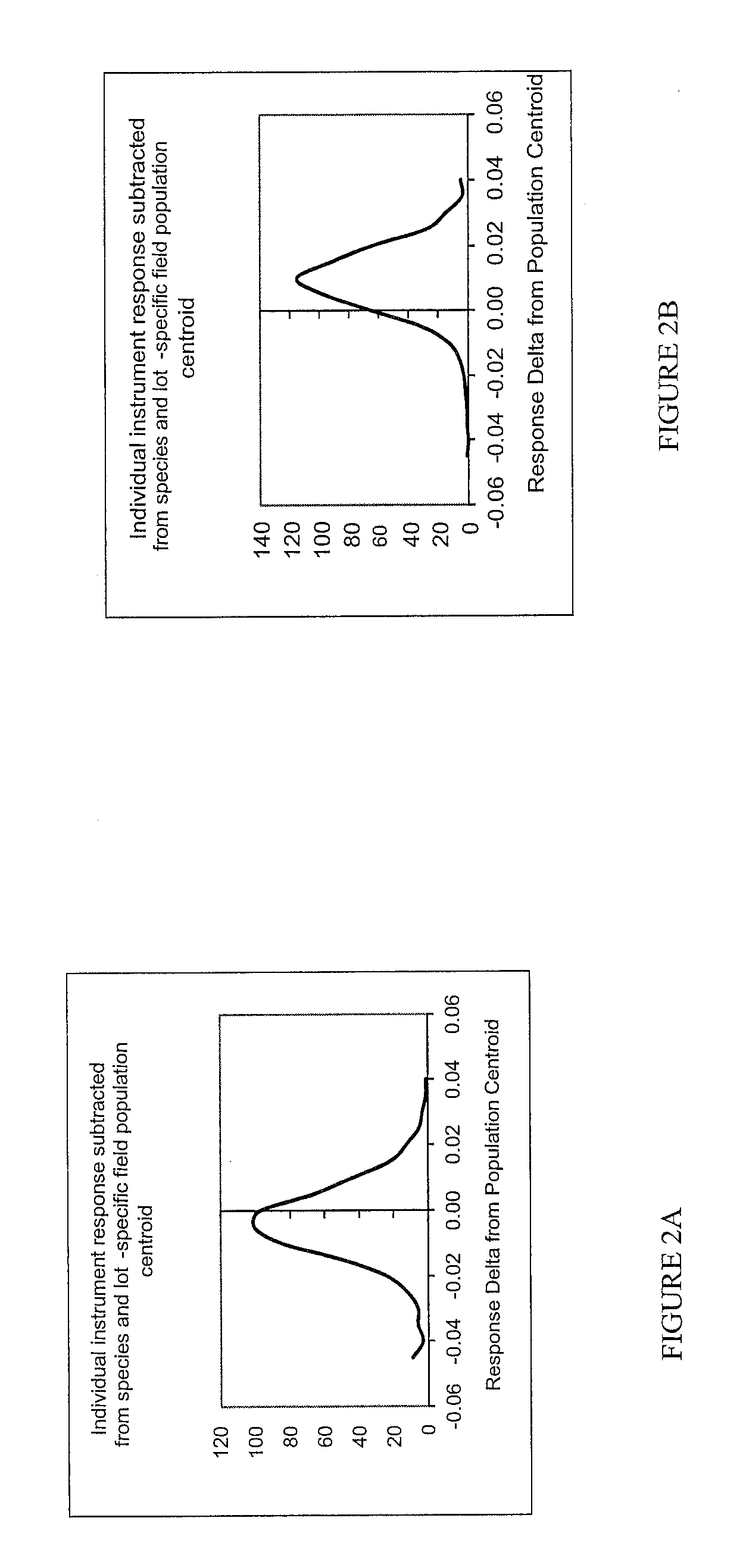
[0028]A preferred form of the method of the present invention, and system implementing the method, will now be described. In accordance with one form of the present invention, an automated method for calibrating in real-time a diagnostic analyzer, such as a blood chemistry analyzer, preferably includes the steps of receiving the diagnostic (e.g., chemistry) results of patient samples calculated by the analyzer using the analyzer's pre-set parameters (such as optical gain, for example), and applying a centroid calculation algorithm (that could manifest as any centrally tending algorithm that identifies the natural center of the data set and could be calculated using average, median, mode, or a more advanced algorithm for finding the center of maximum density) to the patient sample diagnostic results to obtain a centroid (median) value representing the instrument response for a particular species on a particular lot. The method further includes the steps of comparing field population ...


PUM


Abstract

An automated method for calibrating in real time a diagnostic analyzer includes the steps of receiving diagnostic results of patient samples calculated by the analyzer using pre-set parameters of the analyzer, and calculating the centroid of the analyzer's diagnostic results. The centroid of the analyzer's diagnostic results is subtracted from a centroid of diagnostic results of a field population of comparable analyzers to obtain a bias in the centroid of the analyzer's diagnostic results. The bias is compared to predetermined limits Should the bias fall outside the predetermined limits, an optimization factor is derived and applied to the analyzer's diagnostic results to obtain optimized results from the analyzer without changing the pre-set parameters of the analyzer.

Description

CROSS-REFERENCE TO RELATED APPLICATIONS[0001]This application is a continuation-in-part of U.S. patent application Ser. No. 12 / 932,192, which was filed on Feb. 18, 2011, and is entitled “Automated Calibration Method and System for a Diagnostic Analyzer”, the disclosure of which is incorporated herein by reference and on which priority is hereby claimed, which prior application is based on U.S. Provisional Application Ser. No. 61 / 398,920, which was filed on Jul. 2, 2010, and is entitled “Automated Calibration Method and System for a Diagnostic Analyzer”, the disclosure of which is hereby incorporated by reference and on which priority is hereby claimed.BACKGROUND OF THE INVENTION[0002]1. Field of the Invention[0003]The present invention generally relates to diagnostic instruments for human and veterinary applications, and more specifically relates to methods and systems for calibrating such instruments.[0004]2. Description of the Prior Art[0005]Diagnostic instruments have been used f...

Claims


Application Information

Patent Timeline
Patent Type & Authority Applications(United States)
IPC IPC(8): G06F19/00
CPCG01N2035/00702G01N35/00693
Inventor HAMMOND, JEREMYPELLETIER, DOMINICAGUIAR, JASON
Owner IDEXX LABORATORIES
Learn More