Low Latency Multi-Detector Noise Cancellation

a multi-detector, low-latency technology, applied in the field of data processing, can solve problems such as large loop noise, and achieve the effect of reducing interferen

Active Publication Date: 2013-01-03
AVAGO TECH INT SALES PTE LTD
View PDF9 Cites 13 Cited by
  • Summary
  • Abstract
  • Description
  • Claims
  • Application Information

AI Technical Summary

Benefits of technology

[0008]Other embodiments of the present invention provide methods for processing data. The methods include providing a first data detector circuit; providing a second data detector circuit; receiving a data input; performing a data detection process using the first data detector circuit on a first signal derived from the data input to yield a detected output; performing a second data detection process using the second data detector circuit on a second signal derived from the data input to yield a second detected output; calculating an error value based on a first error signal derived from the detected output and on a second error signal derived from the second detected output; generating a feedback signal based at least in part on the error value; and applying the feedback signal to modify the data input. In some cases, the latency between the data input and the first error signal is greater than the latency between the data input and the second error signal. In various cases, the error value is calculated by applying a delay to the second error signal to yield a delayed second error signal; subtracting the delayed second error signal from the first error signal to yield a corrected error signal; and adding the second error signal to the corrected error signal to yield the error value. In various cases, the second data detection process comprises reducing interference evident in a current bit that is related to at least one preceding bit in a bit stream using a decision feedback equalizer. In various cases, the methods also include replacing the feedback signal with digital samples of the data input when not in a tracking mode.

Problems solved by technology

A low latency loop may be used to track low frequency changes in the data signal, although conventional low latency loops often introduce excessive errors leading to large loop noise.

Method used


Image

  • Low Latency Multi-Detector Noise Cancellation
  • Low Latency Multi-Detector Noise Cancellation
  • Low Latency Multi-Detector Noise Cancellation

Examples


Embodiment Construction

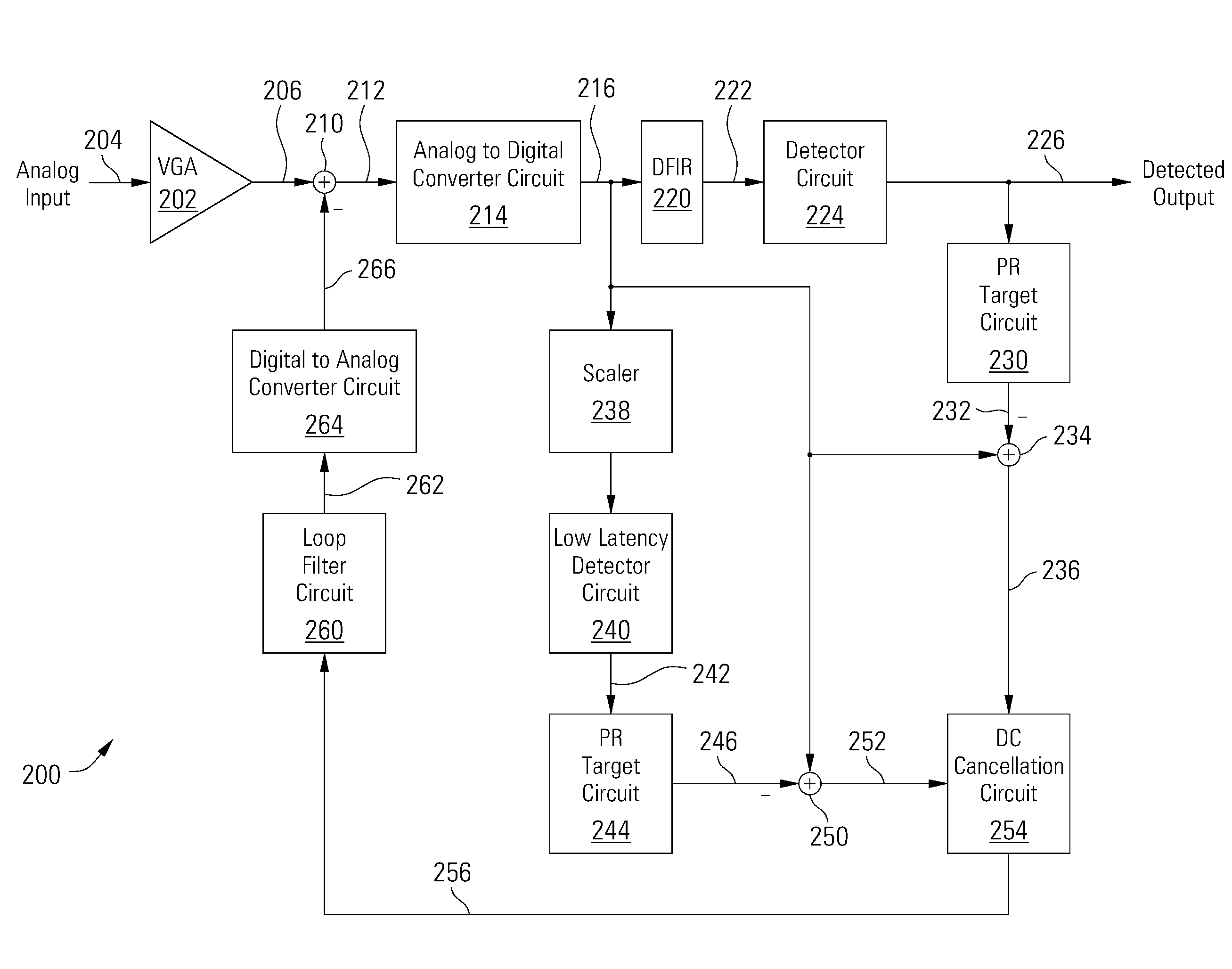
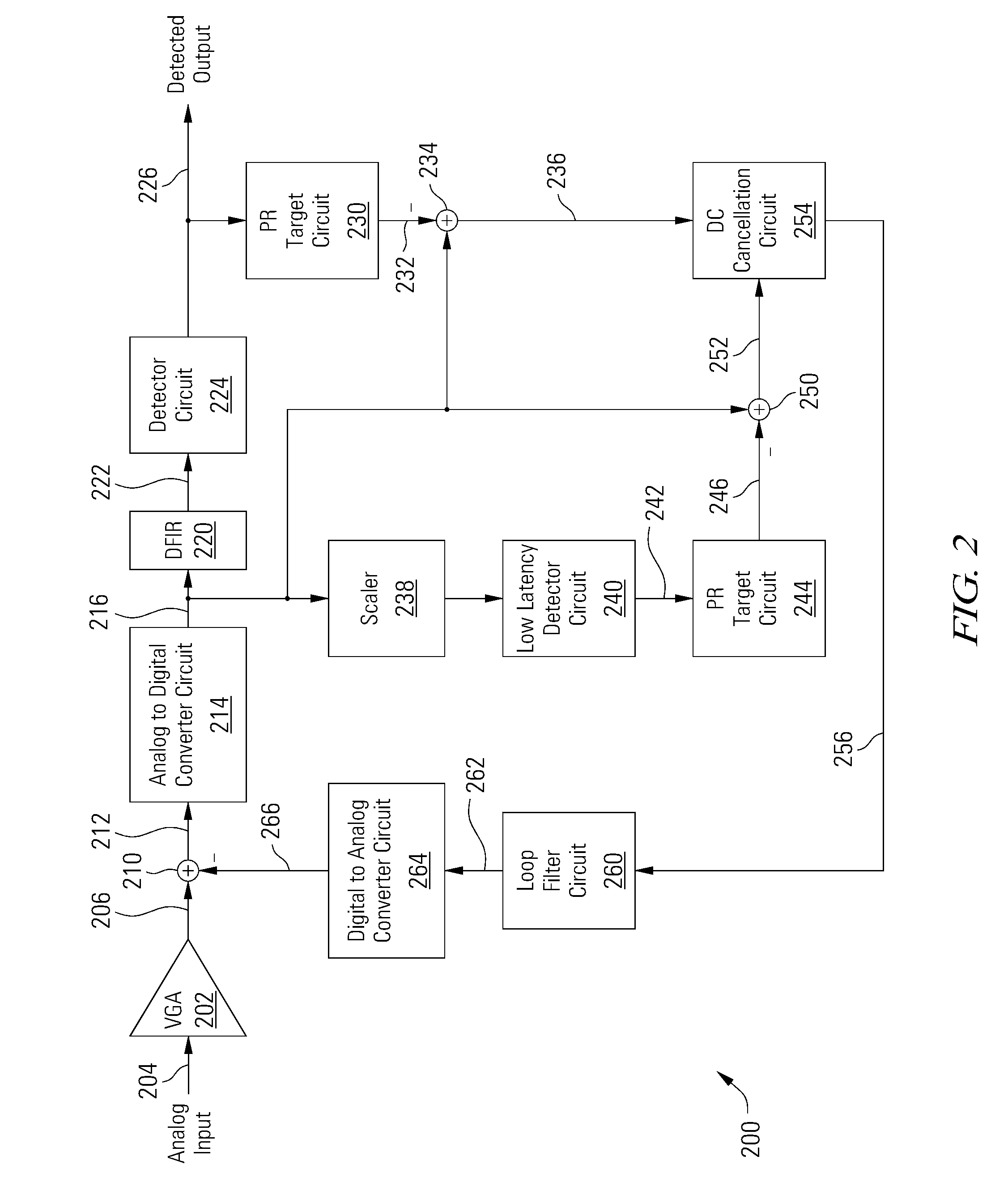
[0022]Various embodiments of the present invention are related to systems and methods for data processing, and more particularly to systems and methods for low latency loop processing.

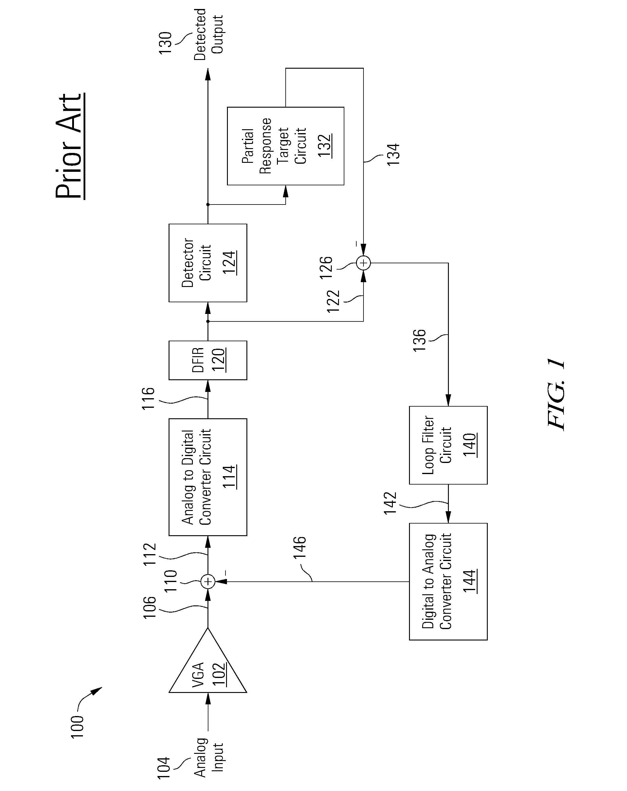
[0023]Turning to FIG. 1, an existing loop circuit 100 is shown that includes low frequency noise correction feedback. Loop circuit 100 includes a variable gain amplifier (VGA) 102 that receives an analog input 104. Variable gain amplifier 102 amplifies analog input 104 to yield an amplified output 106 that is provided to a summation circuit 110. Summation circuit 110 subtracts a feedback signal 146 from amplified output 106 to yield a sum 112.

[0024]Sum 112 is provided to an analog to digital converter circuit (ADC) 114 that converts the received signal into a series of digital samples 116 that are provided to a digital finite impulse response (DFIR) filter 120. Digital finite impulse response filter 120 acts as an equalizer and filters the received input to provide a corresponding filtered output 122 t...


PUM


Abstract

Various embodiments of the present invention provide systems and methods for data processing. For example, a data processing circuit is disclosed that includes first and second data detectors and an error cancellation circuit. The first data detector is operable to perform a data detection process on a first signal derived from a data input to yield a detected output. The second data detector circuit is operable to perform a data detection process on a second signal derived from the data input to yield a second detected output. The error cancellation circuit is operable to combine a first error signal derived from the detected output with a second error signal derived from the second detected output to yield a feedback signal. The feedback signal is operable to modify the data input during a subsequent period.

Description

BACKGROUND[0001]Various embodiments of the present invention are related to systems and methods for data processing, and more particularly to systems and methods for low latency loop processing.[0002]Various data processing circuits have been developed that include one or more loops. For example, a data signal may be processed by a data processing circuit in a loop in which information is fed back into itself. A loop that can track low frequency changes in the data signal requires a relatively large loop update gain, which is generally not available from a high latency loop. A low latency loop may be used to track low frequency changes in the data signal, although conventional low latency loops often introduce excessive errors leading to large loop noise.[0003]Hence, for at least the aforementioned reasons, there exists a need in the art for advanced systems and methods for data processing.BRIEF SUMMARY[0004]Various embodiments of the present invention are related to systems and met...

Claims


Application Information

Patent Timeline
Patent Type & Authority Applications(United States)
IPC IPC(8): G06F11/16
CPCG11B20/10055G11B2220/2516G11B20/10296
Inventor SEAGO, BRADLEY D.DZIAK, SCOTT M.LIU, JINGFENG
Owner AVAGO TECH INT SALES PTE LTD
Why Eureka
Try Eureka