Swing brake control apparatus for construction machinery

a technology for controlling apparatus and construction machinery, applied in the direction of braking system, fluid coupling, coupling, etc., can solve the problems of low efficiency and damage to equipment, loss of life, occurrence of undesired swinging, etc., to prevent damage to the swing motor or the swing brake, and prevent an accident

Active Publication Date: 2013-01-10
DOOSAN INFRACORE CO LTD
View PDF1 Cites 6 Cited by
  • Summary
  • Abstract
  • Description
  • Claims
  • Application Information

AI Technical Summary

Benefits of technology

[0014]Accordingly, the present disclosure is proposed on the basis of the points described above, and provides a swing brake control apparatus for construction machinery, which can avoid a clash between the operations of a swing motor and a swing brake of construction machinery during the driving of the swing motor, so as to prevent damage to the swing motor or the swing brake, or prevent an accident from occurring.

Problems solved by technology

According to the work characteristics of an excavator, the occurrence of undesired swinging can lead not only to lower efficiency and damage to equipment, but also to the loss of life.
A representative example is the occasional occurrence of undesired swinging when a vehicle is positioned or working on a slope while the engine is stopped or idling.
Further, equipment damage and loss of life can be caused by a clash between the driving of a swing motor and the stopping of a brake when a swing brake operates while an operator is performing or begins to implement a swinging operation.
However, in the case of hybrid excavators, because the hydraulic swing motor has been changed to an electric swing motor so as to omit the hydraulic line from the swing system, a hydraulic signal according to the movement of a swing joystick cannot actuate the electric swing motor.
Thus, there arise the problems of damage and accidents due to a clash between the operations of the swing motor and the swing brake, when the swing motor is operated before or during the disengaging of the swing brake.

Method used


Image

  • Swing brake control apparatus for construction machinery
  • Swing brake control apparatus for construction machinery
  • Swing brake control apparatus for construction machinery

Examples


Embodiment Construction

[0028]Hereinafter, a swing brake control apparatus for construction machinery according to exemplary embodiments of the present disclosure will be described in detail.

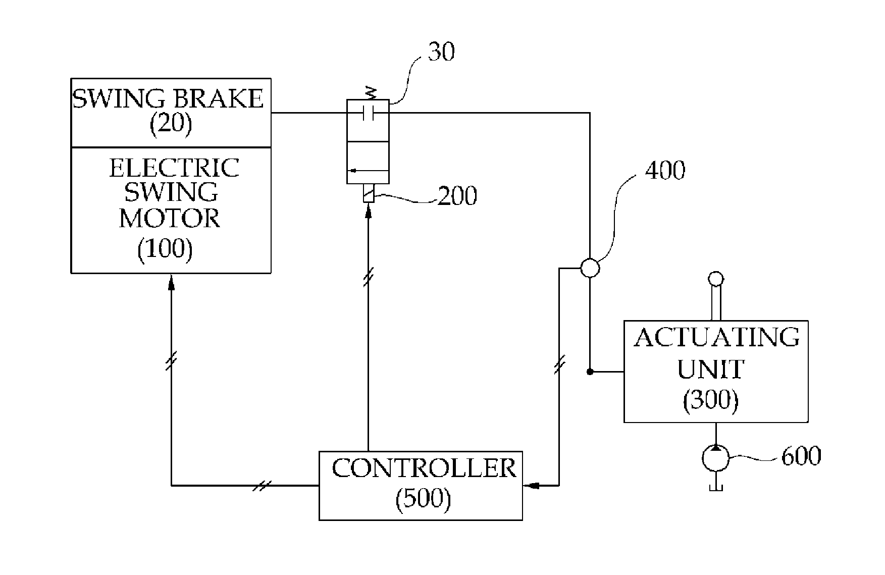
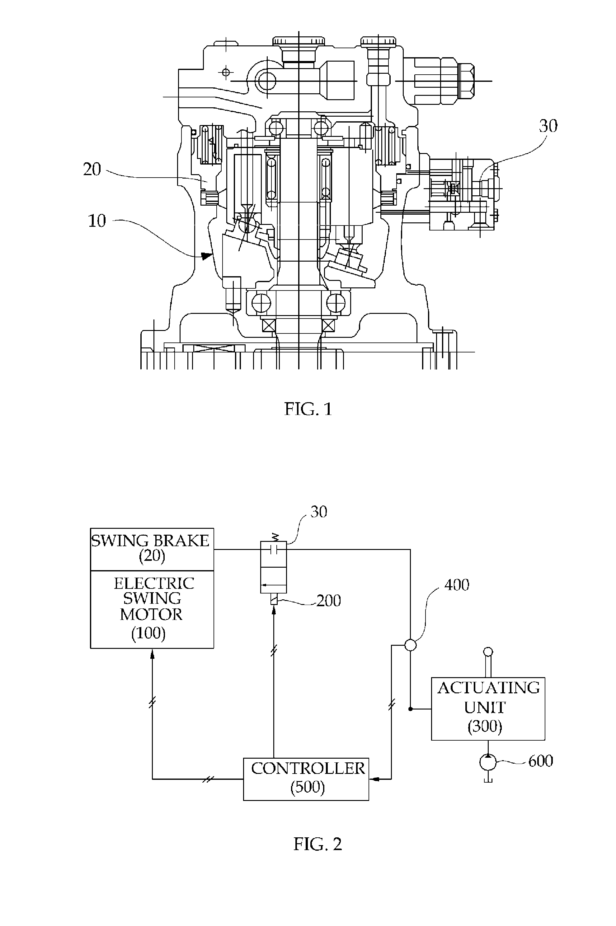
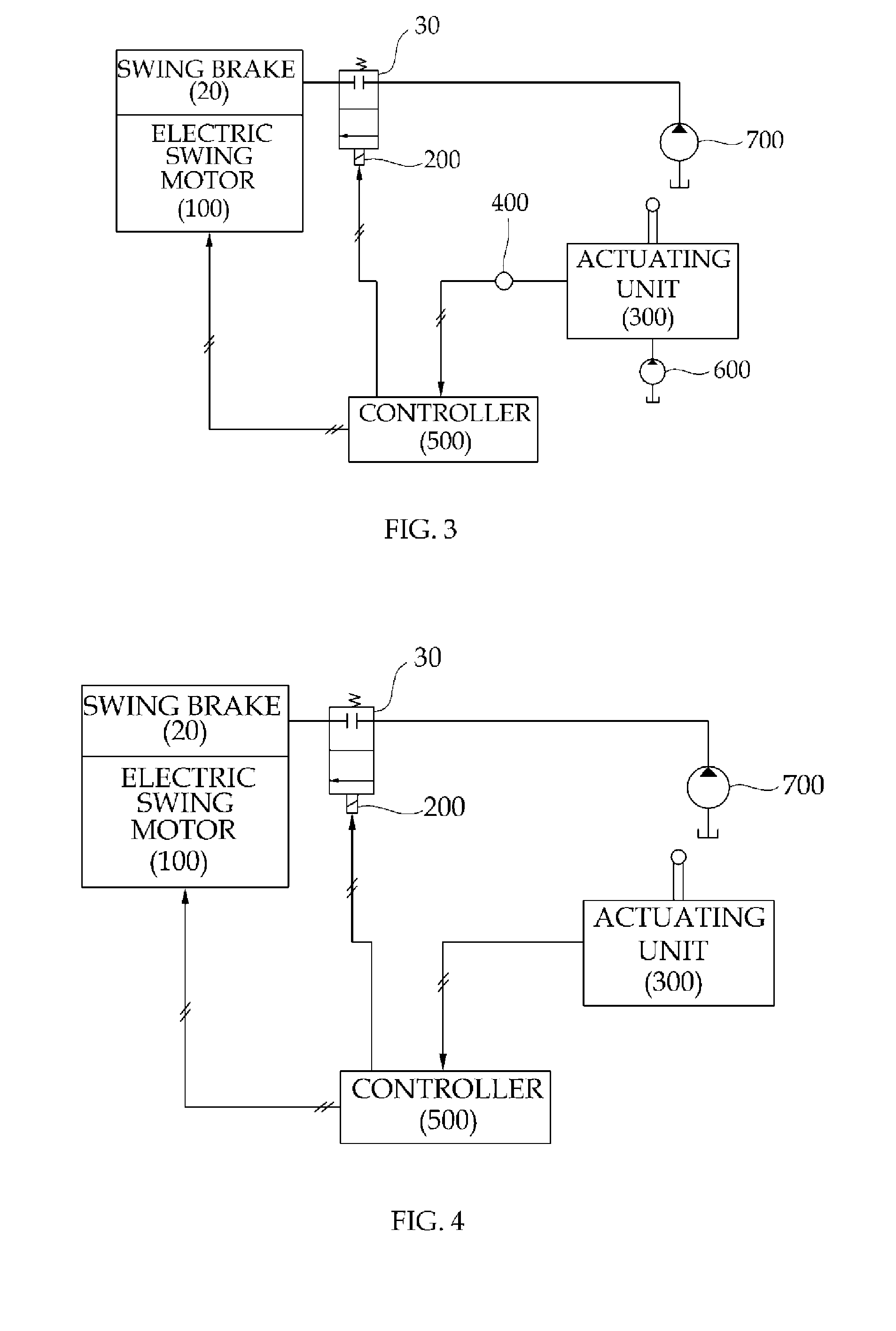
[0029]Referring to FIG. 2, according to an exemplary embodiment of the present disclosure, a swing brake control apparatus for construction machinery, for a swing brake apparatus for the construction machinery having a lower moving body, and an upper swing body supported to be capable of swinging on the lower moving body, includes: a swing motor 100 configured to drive the upper swing body; a swing brake 20 configured to stop the swing motor 100; a swing brake valve 30 configured to vary and control actuation and disengaging of the swing brake 20; a solenoid valve 200 provided on the swing brake valve 30 and configured to control the varying of the swing brake valve 30; a swing actuating unit 300 configured to actuate driving of the upper swing body; an actuation sensor 400 configured to sense a movement of the swing a...


PUM


Abstract

The present disclosure relates to an apparatus for controlling a swing brake for construction machinery, comprising: a lower travel body; an upper swinging body supported at the lower travel body such that the upper swing body is capable of being swung; a swing motor for driving the upper swing body; a swing brake for braking the swing motor; a swing brake valve which operates to control the braking and releasing operations of the swing brake; a solenoid valve mounted on the swing brake valve to control the operation of the swing brake valve; an operation sensor which applies a first reference signal and a second reference signal in accordance with the motion of a swing operation control unit for controlling the operation of the upper swinging body, wherein said second reference signal is generated when an amount of displacement of the swing operation control unit is larger than the first reference signal; and a control unit, which operates the swing brake valve to release the swing brake when the first reference signal is inputted from the operation sensor, and which operates the swing motor when the second reference signal is inputted.

Description

[0001]This Application is a Section 371 National Stage Application of International Application No. PCT / KR2010 / 009237, filed Dec. 23, 2010 and published, not in English, as WO2011 / 078587 on Jun. 30, 2011.FIELD OF THE DISCLOSURE[0002]The present disclosure relates to construction machinery such as an excavator, and particularly, to a swing brake control apparatus for construction machinery, devised to release a swing brake of a hybrid excavator, in order to stably control a swing motor and a swing brake, when the construction machinery is configured with an electric swing motor and a hydraulic swing brake.BACKGROUND OF THE DISCLOSURE[0003]In general, in order to improve work efficiency and working range, construction machinery such as excavators have an upper swing body installed to be capable of swinging on a lower moving body. The upper swing body is stopped by means of a swing brake apparatus, so that the operator may control the swinging of the upper swing body. An example of suc...

Claims


Application Information

Patent Timeline
Patent Type & Authority Applications(United States)
IPC IPC(8): F15B15/18
CPCE02F9/128F15B2211/6316F15B2211/6346F15B2211/7058B60T13/686F15B2211/851B60T13/141B60T13/662F15B2211/715
Inventor KIM, KYEONG KEUN
Owner DOOSAN INFRACORE CO LTD
Why Eureka
Try Eureka