Spray nozzle and method for the production of at least one rotating spray jet

a technology of spray nozzle and spray nozzle, which is applied in the direction of movable spraying apparatus, botany apparatus and processes, etc., can solve the problems of increasing the impulse and increasing the cleaning power, unable to achieve sufficient cleaning or coating efficiency, and the dwell time of the spray jet on the surface to be cleaned or coated is then too short to achieve the required effect, so as to prevent the build-up of incrustations and prevent the accumulation of incrustations or deposits

Inactive Publication Date: 2013-01-10
LECHLER SPA
View PDF4 Cites 2 Cited by
  • Summary
  • Abstract
  • Description
  • Claims
  • Application Information

AI Technical Summary

Benefits of technology

[0015]The provision of a drip point can prevent the build-up of incrustations on the nozzle. When the fluid supply to the spray nozzle of the invention has been turned off, fluid adhering to the nozzle can drip off rapidly and centrally by way of the drip point, in order to prevent the build-up of incrustations or deposits on the nozzle.
[0016]In a development of the invention, a longitudinal center axis of a spray jet emerging from the at least one outlet orifice on the rotor is disposed such that the emergent spray jet, by virtue of its recoil force, either accelerates, or has no effect on, the rotation of the rotor.

Problems solved by technology

This smearing effect as occurs when a rotor rotates too rapidly refers to the extremely fast sweeping movement of the spray jet over an area to be cleaned or to be coated, with the result that it is no longer possible to achieve sufficient cleaning or coating efficiency.
The dwell time of the spray jet on a surface to be cleaned or coated is then too short to achieve the required effect.
Although an increase in the fluid pressure in conventional rotating cleaning nozzles results in a spray jet having a greater impulse and an increased cleaning power per se, the smearing effect of such nozzles prevents satisfactory cleaning efficiency from being achieved.

Method used


Image

  • Spray nozzle and method for the production of at least one rotating spray jet
  • Spray nozzle and method for the production of at least one rotating spray jet
  • Spray nozzle and method for the production of at least one rotating spray jet

Examples


Embodiment Construction

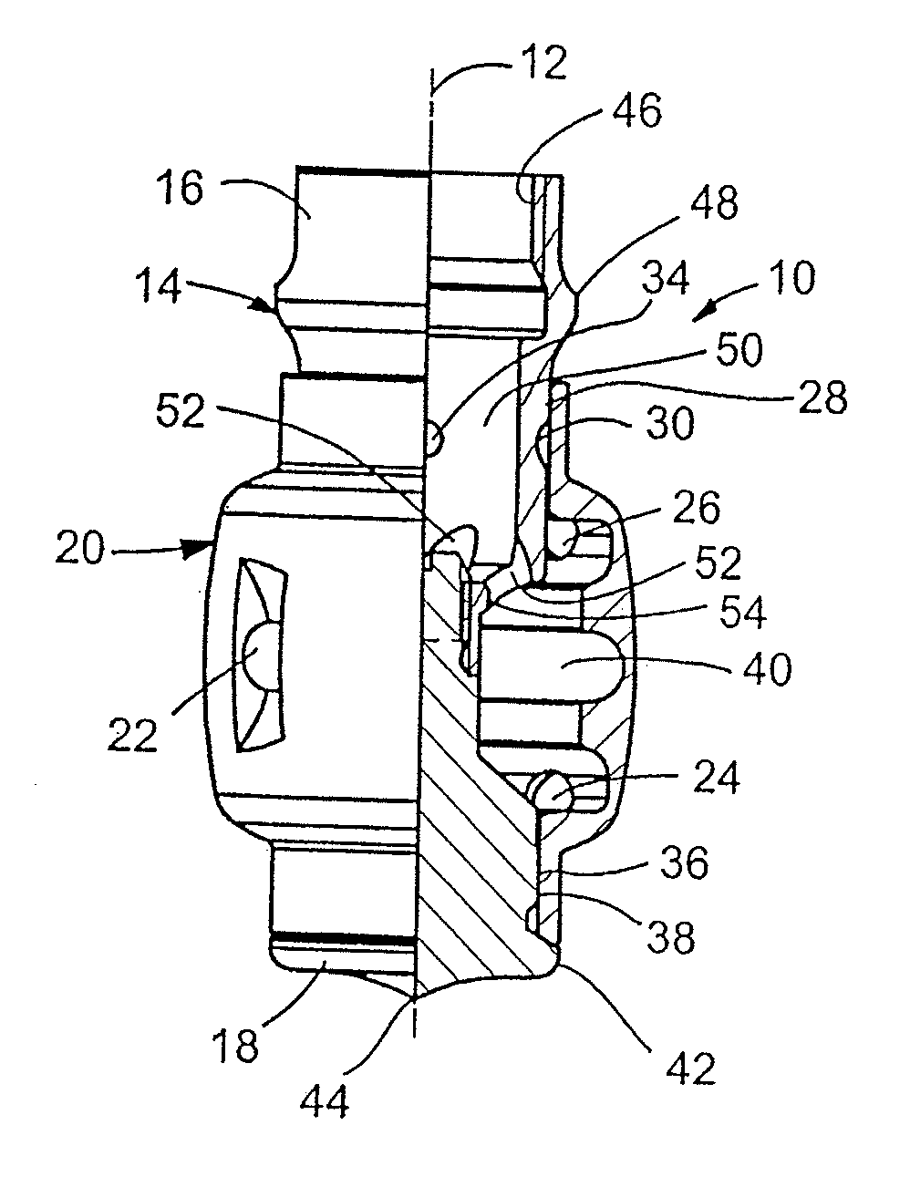
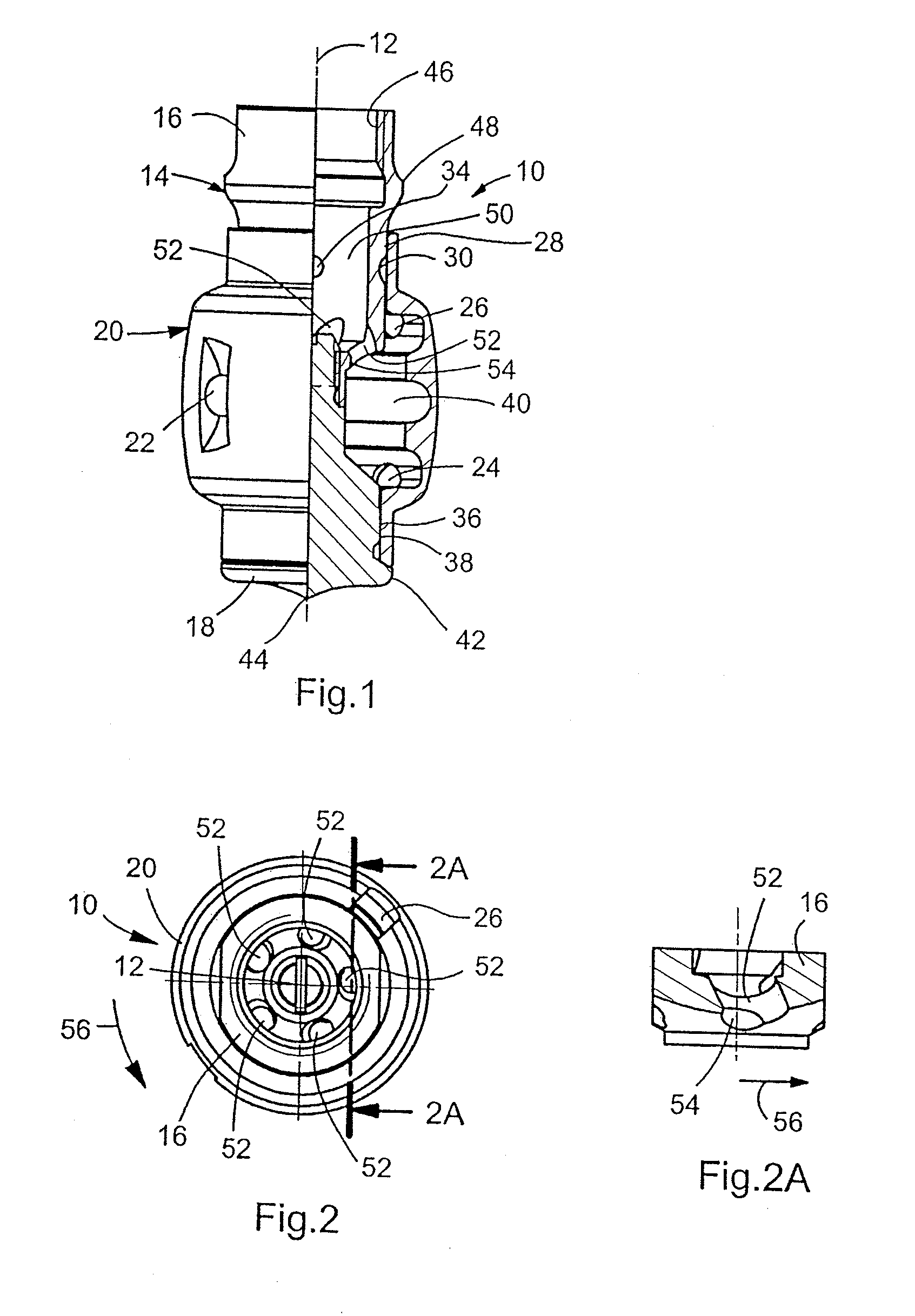
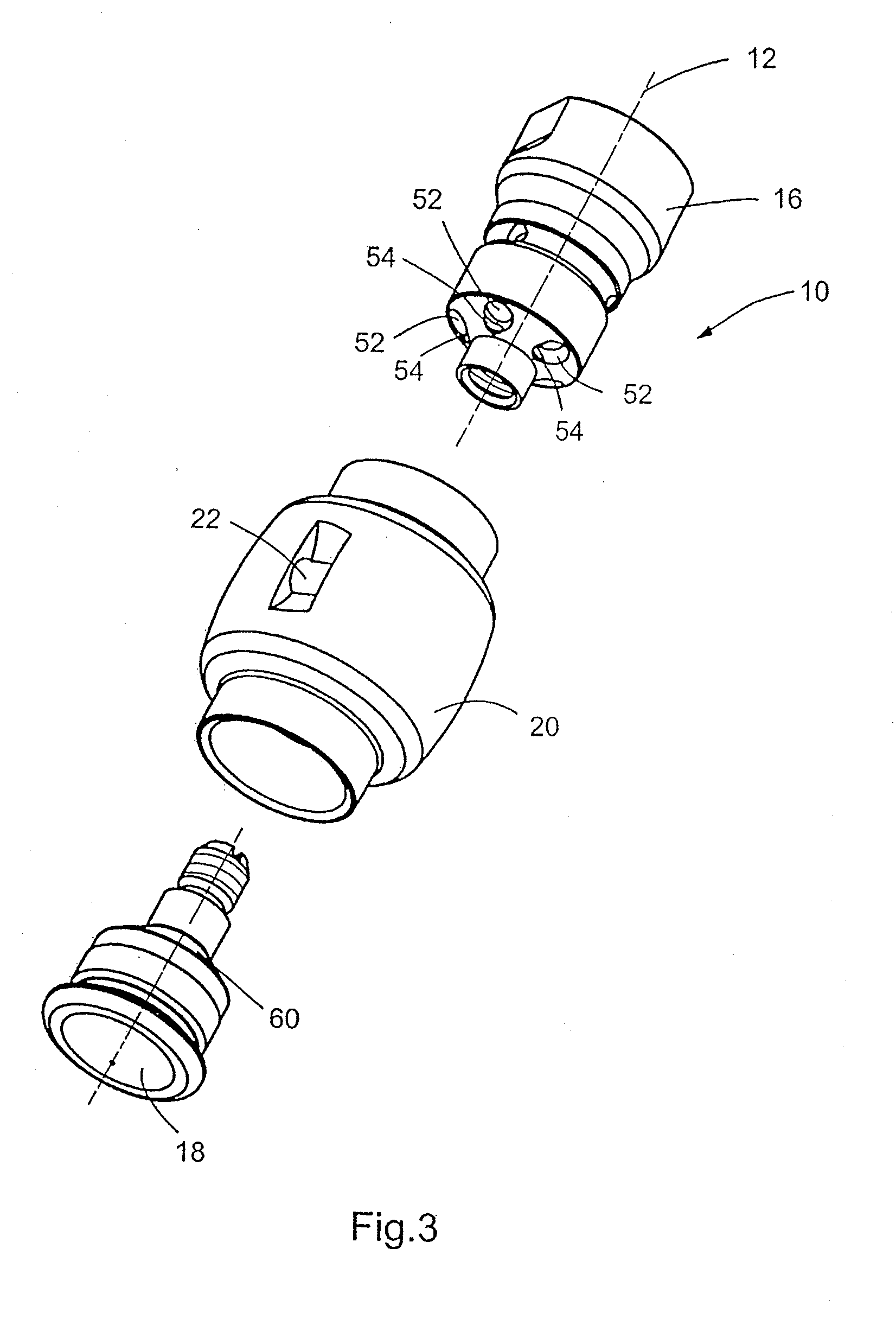
[0031]FIG. 1 illustrates a spray nozzle 10 of the invention, the spray nozzle being shown as a side view in the left half of FIG. 1 and as a cross-sectional view in the right half of FIG. 1. The cross-sectional plane shown is parallel to the drawing surface and contains the longitudinal center axis 12 of the nozzle. The spray nozzle 10 of the invention comprises a housing 14 consisting of a first housing portion disposed at the top of FIG. 1, and a second housing portion 18 disposed at the bottom of FIG. 1. The spray nozzle 10 further comprises a rotor 20 that is mounted for rotation on the housing 14 and partially surrounds the same.

[0032]The rotor 20 is provided with a plurality of outlet orifices 22, 24, and 26. The outlet orifice 22 is disposed approximately opposite to the two outlet orifices 24 and 26 on the rotor 20, as regarded in the peripheral direction of the rotor 20.

[0033]As can be seen from the right half of FIG. 1, the second housing portion 18 is screwed into a suita...


PUM


Abstract

A spray nozzle for the production of at least one rotating spray jet, comprising a housing comprising a fluid inlet and a rotor mounted for rotation on the housing and comprising at least one discharge orifice for the fluid to be sprayed, wherein a swirl chamber is provided between the housing and the rotor and wherein the fluid to be sprayed is fed to the swirl chamber by way of at least one inlet duct inclined in the required direction of rotation of the rotor, in which the inlet duct has, at its end opening into the swirl chamber, a widened portion, which widened portion of the end of the inlet duct is disposed on the counter-rotative side of that end of the inlet duct which opens into the swirl chamber.

Description

CROSS REFERENCE TO RELATED APPLICATION[0001]This application claims the priority of German Application No. 10 2011 078 857.3, filed Jul. 8, 2011, the disclosure of which is hereby incorporated by reference in its entirety into this application.FIELD OF THE INVENTION[0002]The invention relates to a spray nozzle for the production of at least one rotating spray jet, which spray nozzle comprises a housing comprising a fluid inlet and a rotor mounted for rotation on the housing and comprising at least one outlet orifice for the fluid to be sprayed, wherein a swirl chamber is provided between the housing and the rotor and wherein the fluid to be sprayed is fed to the swirl chamber by means of at least one inlet duct that is inclined in the required direction of rotation of the rotor.[0003]The invention also relates to a method for the production of at least one rotating spray jet by means of a spray nozzle.BACKGROUND OF THE INVENTION[0004]German Patent Specification DE 100 06 864 B4 disc...

Claims


Application Information

Patent Timeline
Patent Type & Authority Applications(United States)
IPC IPC(8): B05B3/04
CPCB05B3/0409B05B3/003B05B3/06
Inventor LANGE, HERMANNPELZ, SIEGMAR
Owner LECHLER SPA
Why Eureka
Try Eureka