Vertical stacked light emitting structure
a light-emitting structure and vertical stack technology, applied in the direction of discharge tube luminescnet screens, discharge tube/lamp details, incadescent envelopes/vessels, etc., can solve the problems of high power consumption, high heat generation, and quick attenuation, and achieve the effect of increasing the light-emitting efficiency of instant disclosur
- Summary
- Abstract
- Description
- Claims
- Application Information
AI Technical Summary
Benefits of technology
Problems solved by technology
Method used
Image

Examples
first embodiment
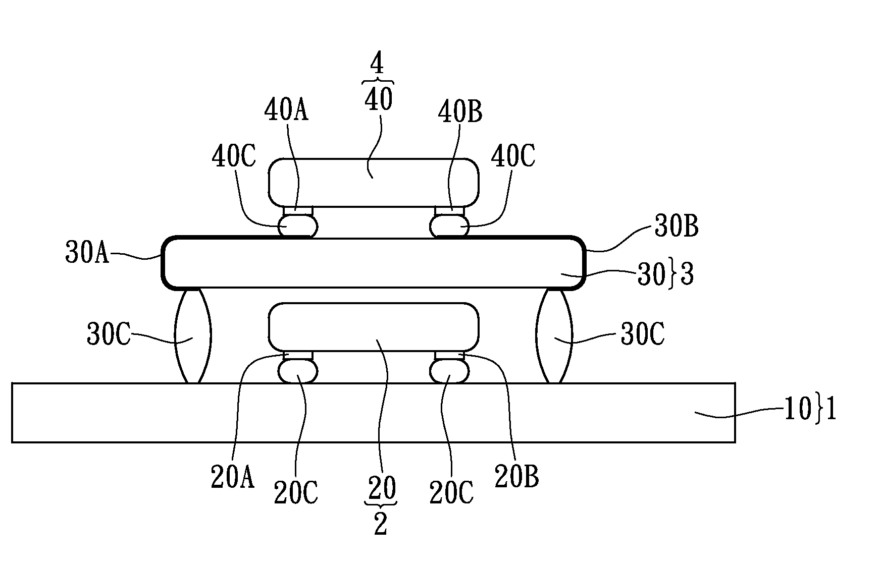
[0027]Referring to FIG. 1, where the first embodiment provides a vertical stacked light emitting structure, comprising: a substrate unit 1, a first light emitting unit 2, a light guiding unit 3, and a second light emitting unit 4. The first light emitting unit 2, the light guiding unit 3, and the second light emitting unit 4 are vertically and upwardly stacked on top of one another sequentially from the substrate unit 1.
[0028]The substrate unit 1 includes at least one substrate body 10. For example, the substrate body 10 may be a circuit substrate, and the circuit substrate has a plurality of conductive traces (not shown) disposed thereon.
[0029]Furthermore, the first light emitting unit 2 includes at least one first LED bare chip 20 disposed on the substrate body 10 and electrically connected to the substrate body 10. Of course, the instant disclosure can use a plurality of first LED bare chips 20 sequentially stacked on top of one another and electrically connected to the substrate...
second embodiment
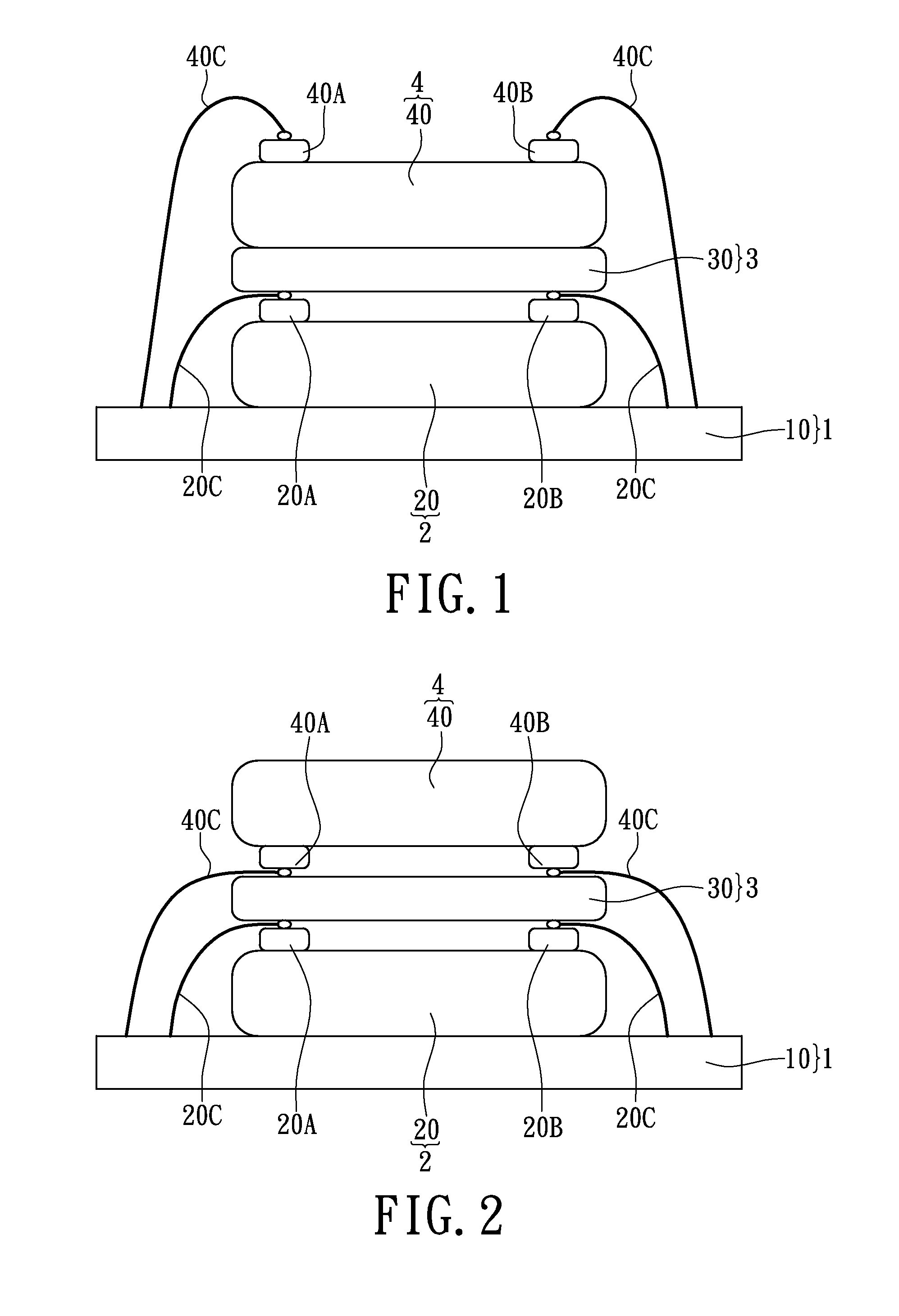
[0032]Referring to FIG. 2, where the second embodiment provides a vertical stacked light emitting structure, comprising: a substrate unit 1, a first light emitting unit 2, a light guiding unit 3, and a second light emitting unit 4. In addition, the first light emitting unit 2 and the light guiding unit 3 are combined to form a stacked type light emitting module, and the second light emitting unit 4 is a flip-chip type light emitting module. Comparing FIG. 2 with FIG. 1, the difference between the second embodiment and the first embodiment is that: in the second embodiment, the second LED bare chip 40 has at least one second positive pad 40A and at least one second negative pad 40B disposed on the bottom surface thereof, the second positive pad 40A and the second negative pad 40B can simultaneously contact the top surface of the light guiding body 30, and at least two second conductive elements 40C (such as metal conductive wires) can be respectively electrically connected between th...
third embodiment
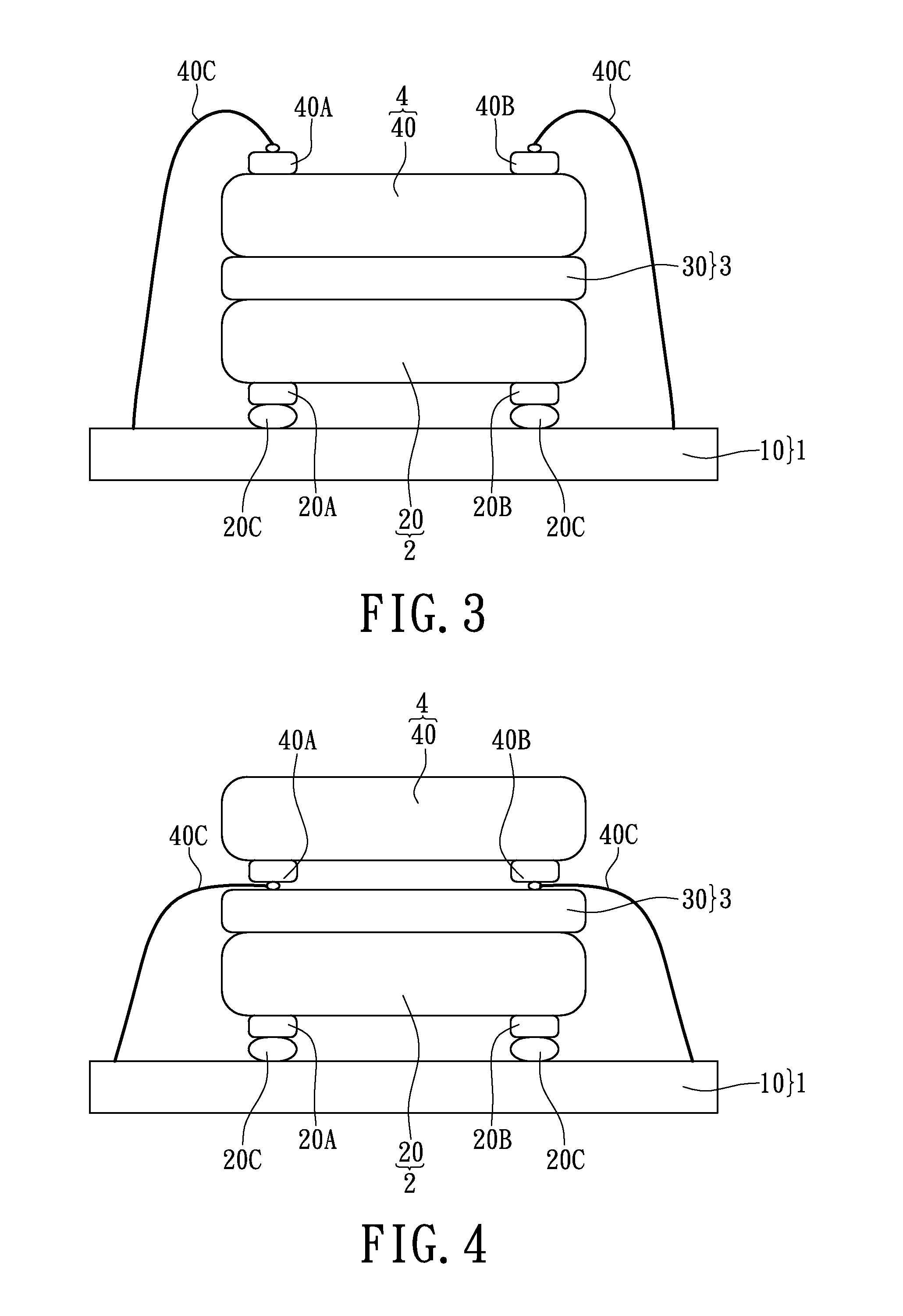
[0033]Referring to FIG. 3, where the third embodiment provides a vertical stacked light emitting structure, comprising: a substrate unit 1, a first light emitting unit 2, a light guiding unit 3, and a second light emitting unit 4. Comparing FIG. 3 with FIG. 1, the difference between the third embodiment and the first embodiment is that: in the third embodiment, the top surface of the first LED bare chip 20 can contact the bottom surface of the light guiding body 30, the first LED bare chip 20 has at least one first positive pad 20A and at least one first negative pad 20B disposed on the bottom surface thereof, and at least two first conductive elements 20C (such as solder balls) are respectively electrically connected between the first positive pad 20A and the substrate body 10 and between the first negative pad 20B and the substrate body 10. For example, the first positive pad 20A and the first negative pad 20B of the first LED bare chip 20 can be electrically connected to the subs...
PUM
 Abstract
Description
Claims
Application Information
 - R&D Engineer
- R&D Manager
- IP Professional
- Industry Leading Data Capabilities
- Powerful AI technology
- Patent DNA Extraction
Browse by: Latest US Patents, China's latest patents, Technical Efficacy Thesaurus, Application Domain, Technology Topic.
© 2024 PatSnap. All rights reserved.Legal|Privacy policy|Modern Slavery Act Transparency Statement|Sitemap