
Systems and methods for extending optical network services across non-optical channels

a technology of optical network and non-optical channels, applied in the field of fiber-to-the-home (ftth), can solve the problems of increasing the installation cost of the service provider of the pon, and the complexity of the pon is relatively high

Active Publication Date: 2013-01-10
ADTRAN
View PDF6 Cites 29 Cited by
  • Summary
  • Abstract
  • Description
  • Claims
  • Application Information

AI Technical Summary

Benefits of technology

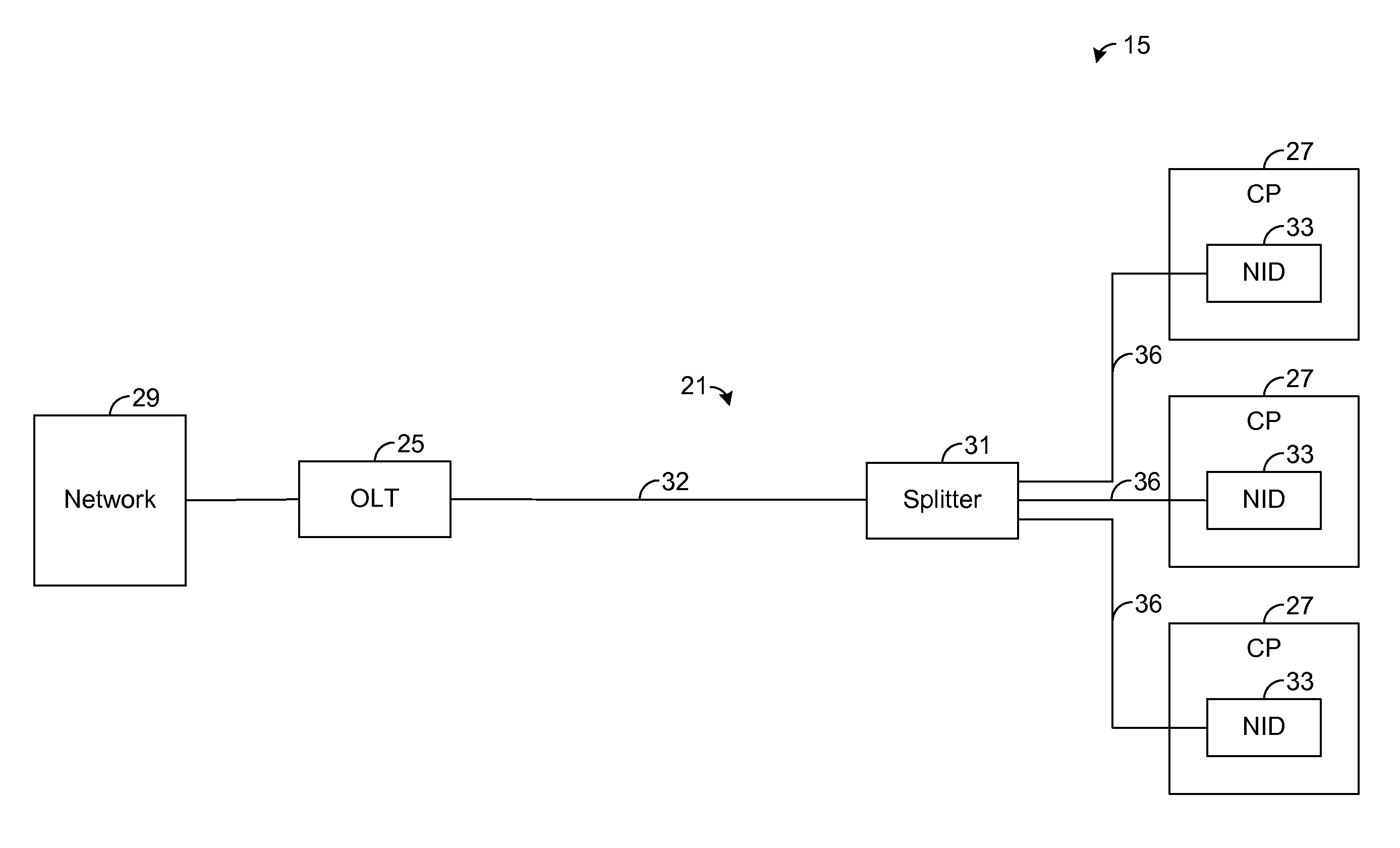
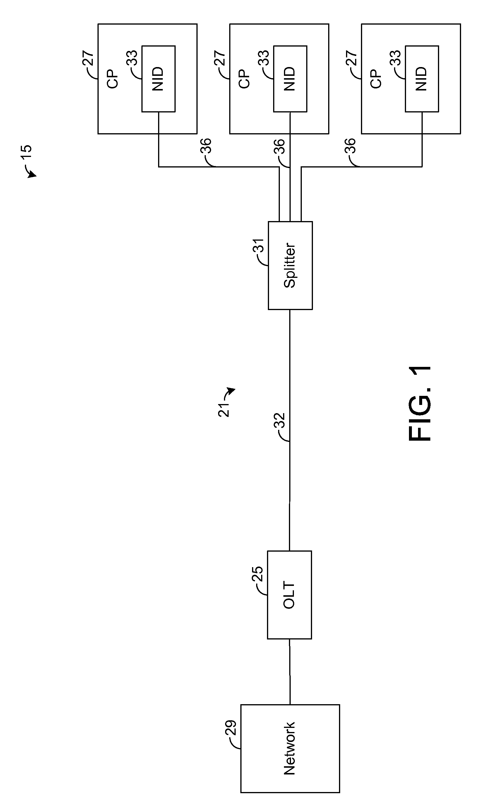
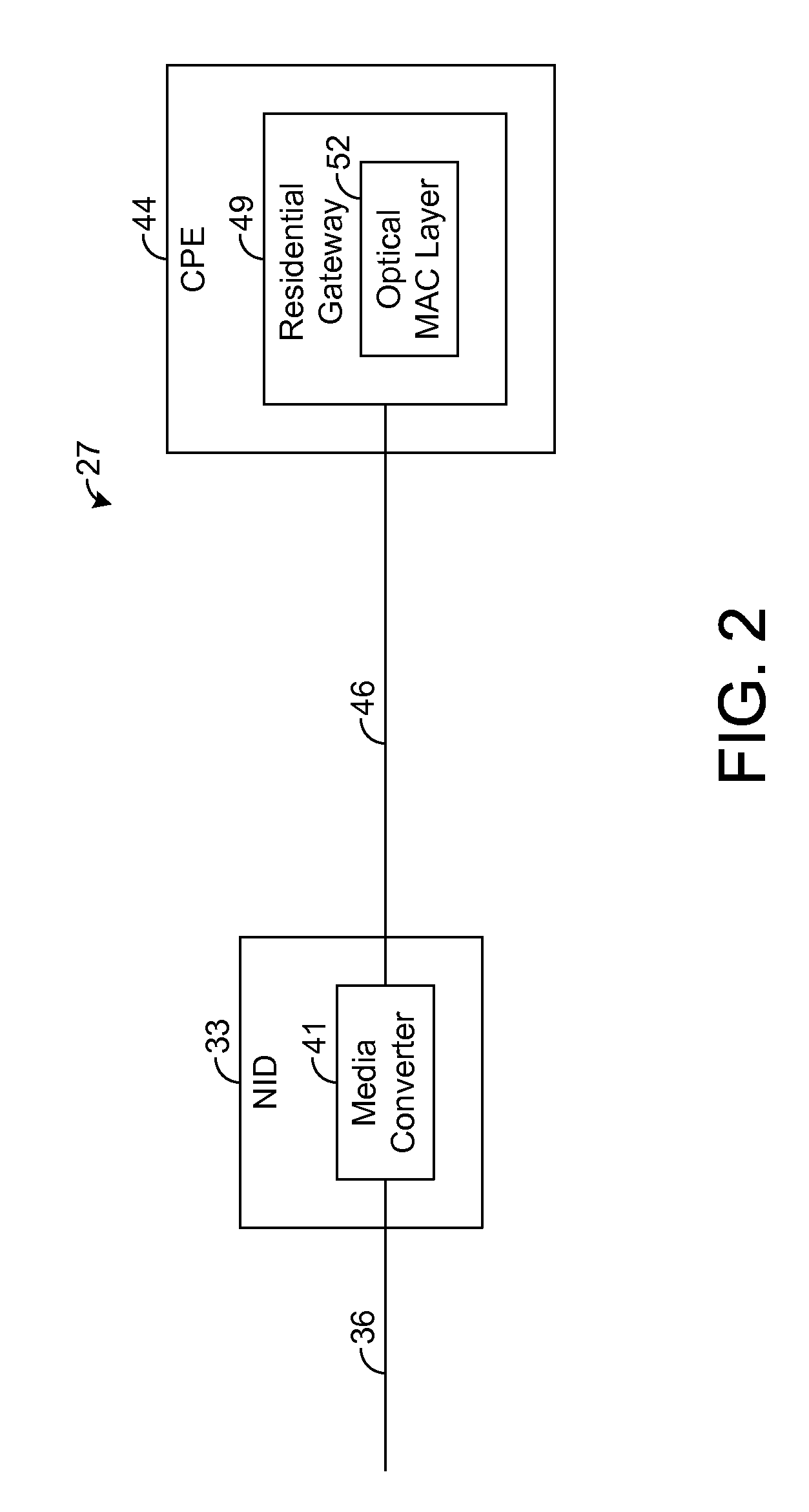
The patent text describes a system and method for extending optical network services to customer premises using a network interface device (NID) and a media converter. The NID is connected to an optical fiber of a passive optical network (PON) and includes an optical MAC layer for handling PON protocols and management. The media converter converts optical signals from the PON into electrical signals for communication across non-optical channels to customer premises equipment (CPE) using conductive or wireless connections. By implementing the optical MAC layer at the CPE, the complexity of the NID is reduced, lowering installation costs. The system also reduces power requirements for the NID by providing sufficient electrical power from the CPE.

Problems solved by technology

The NID is a relatively complex device that has an optical PON interface toward the network, and a non-optical interface toward the user.
Unfortunately, the formatting, communicating, and managing operations performed by the NID require complex circuitry that is relatively expensive and has relatively high power requirements, thereby increasing installation costs to a service provider of the PON.

Method used


Image

  • Systems and methods for extending optical network services across non-optical channels
  • Systems and methods for extending optical network services across non-optical channels
  • Systems and methods for extending optical network services across non-optical channels

Examples


Embodiment Construction

[0014]The present disclosure generally pertains to systems and methods for extending optical network services across non-optical channels, such as conductive or wireless connections. In one exemplary embodiment, a network interface device (NID) at a customer premises has a media converter coupled to an optical fiber of a passive optical network (PON). The media converter converts optical signals from the PON into electrical signals for communication across at least one non-optical channel to customer premises equipment (CPE), such as a residential gateway or other customer premises (CP) device. Rather than implementing an optical media access control (optical MAC) layer in the NID, an optical MAC layer for handling PON protocols and management is implemented by a CP device, thereby effectively extending the customer end of the PON across at least one non-optical connection to the CP device. By implementing the optical MAC layer at the CP device, the complexity of the NID is reduced,...


PUM


Abstract

An optical communication system comprises a network interface device (NID) having a media converter coupled to an optical fiber of a passive optical network (PON). The media converter converts optical signals from the PON into electrical signals for communication across at least one non-optical channel, such as a conductive or wireless connection, to customer premises equipment (CPE), such as a residential gateway or other customer premises (CP) device. Rather than implementing an optical media access control (optical MAC) layer in the NID, an optical MAC layer for handling PON protocols and management is implemented by the CPE, thereby effectively extending the customer end of the PON across at least one non-optical connection to the CPE. By implementing the optical MAC layer at the CPE, the complexity of the NID is reduced thereby lowering the cost of the NID. In one embodiment, in an effort to further reduce the complexity of the NID, the optical MAC layer is configured to control a laser-on state of an optical transmitter in the NID.

Description

RELATED ART[0001]In a traditional fiber-to-the-home (FTTH) architecture, a network interface device (NID) with ONU functionality is typically installed on a side of a customer's house in order to terminate a passive optical network (PON) connection. The NID is a relatively complex device that has an optical PON interface toward the network, and a non-optical interface toward the user. The optical portion of the NID includes an optical media access control (optical MAC) layer for handling PON protocols and management. The optical MAC layer converts between physical layer optical signals and distinct data units, such as Ethernet frames. The non-optical portion of the NID includes a non-optical media access control (non-optical MAC) layer for handling non-optical protocols and management. The non-optical MAC layer converts between physical layer non-optical signals and distinct data units, such as Ethernet frames.[0002]In the downstream direction, the optical MAC layer in the NID recei...

Claims


Application Information

Patent Timeline
IPC IPC(8): H04J14/08
CPCH04Q11/0067H04B10/272H04Q2011/0064H04Q11/0071H04B10/27
Inventor GOODSON, RICHARDSANDSTROM, LEIF J.SCHNEIDER, KEVIN W.
Owner ADTRAN
Learn More