Chromatography apparatus having diffusion-bonded and surface-modified components

Active Publication Date: 2013-01-17
WATERS TECH CORP
View PDF5 Cites 23 Cited by
  • Summary
  • Abstract
  • Description
  • Claims
  • Application Information

AI Technical Summary

Benefits of technology

[0022]There are numerous advantages of aspects of the present technology including, but not limited to, the ability to economically fabricate a chromatographic device capable of withstanding high internal pressures, in particular the high pressures associated with modern small-particle chromatographic separations. In addition, some aspects of the present technology provide advantageous fabrication methods, which lend themsel

Problems solved by technology

The existence of volumes external to the column (for example, in transport tubing, in detectors, and in injectors) generally can only degrade the quality of a separation as delivered by a column.
Stated another way, extra-column volumes and extra-column variances that are acceptable in the practice of conventional HPLC are generally inappropriate in the practice of capillary and nanoscale LC techniques.
Capillary and nanoscale techniques are at the forefront of separations technology at this time, largely because of their suitability for interfacing with mass spectrometry, particularly where the available samp

Method used


Image

  • Chromatography apparatus having diffusion-bonded and surface-modified components
  • Chromatography apparatus having diffusion-bonded and surface-modified components
  • Chromatography apparatus having diffusion-bonded and surface-modified components

Examples


Example

[0077]In a first embodiment (shown in FIGS. 5A-5E), the channel that is to be packed terminates into a narrower channel that creates a restriction at which particles will be retained. A first photolithographic operation creates mask opening 500 (FIG. 5A). Electroetching through this opening creates channel 501, also shown in cross-section in 505 (FIG. 5D). A second photolithographic operation (FIG. 5B) creates a narrower mask opening 502. Electroetching through this opening creates narrow channel 503, also shown in cross-section in 506 (FIG. 5E). The shape and size of the two channels are determined by the width of the mask opening defined by photolithography and by the amount of electrical charge provided to the electrolytic cell by the electrical power supply. The depth of channel 506 can be made as small as 1 micrometer and can thus be a physical barrier for micrometer-size particles. However, such a shallow flow passage can easily be clogged by debris or precipitates from the so...

Example

[0078]In a second embodiment (shown in FIGS. 6A-6C), a mask opening 601 for the narrow channel is shifted slightly relative to the channel 600 by a small distance 602 (FIG. 6A). If this distance is determined appropriately, a neck 604 is created between channels 600 and 603 by electroetching through mask opening 602 (FIG. 6B). The gap between the top plane 605 of the metal sheet and the top of the neck 606 is ideally between 1 and 5 micrometers (FIG. 6C).

Example

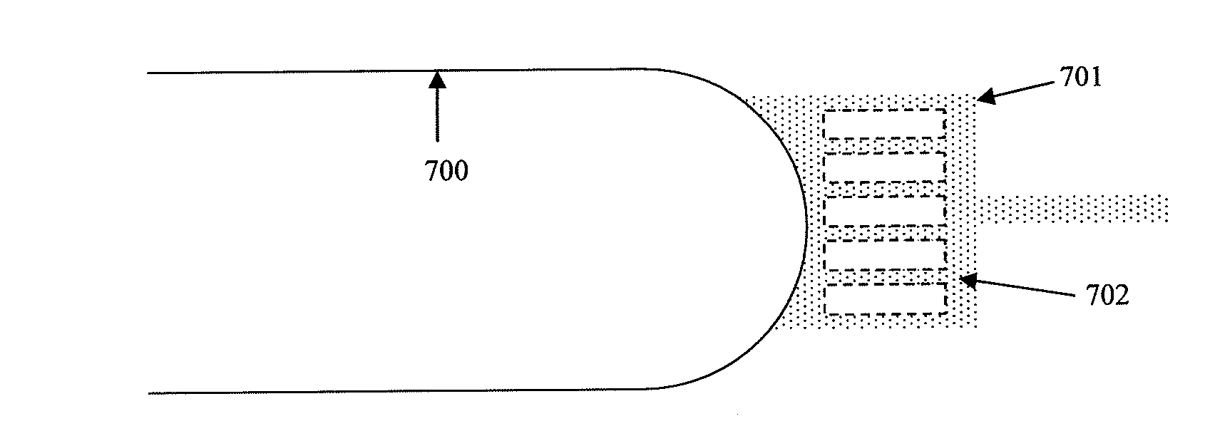
[0079]In the third embodiment (shown in FIGS. 7A-7D), after the channel to be packed 700 is first made, with cross-section as seen in 705 (in FIG. 7C), a second photolithography operation creates a pattern 701 (FIG. 7A). The dotted area represents the open part of the mask (FIG. 7A), which is electroetched to form a shallow region 703 of depth 1-5 micrometers (FIG. 7B). The masked features 702 result in weir structures 704, which act as retaining structures for the particles. The plurality of weirs 704 reduces the risk of clogging or flow blockage. A cross-sectional view of weirs 704 is shown in FIG. 7D.

[0080]The outlet of a chromatographic separation column may be directed to the inlet of a mass spectrometer for analysis, a common technique for ionization of the liquid sample being the formation of a Taylor cone at the tip of electrospray nozzle, also commonly referred to as electrospray tip or emitter. In the case of planar microfluidic chromatographic devices, external, such as c...


PUM

PropertyMeasurementUnit
Temperatureaaaaaaaaaa
Compositionaaaaaaaaaa
Melting pointaaaaaaaaaa

Abstract

A microfluidic device for separating a sample by chromatography includes diffusion bonded metallic sheets joined together to create a hermetically sealed interface between each adjacent metallic sheet without the introduction of a secondary material. Enclosed within the diffusion bonded sheets is a separation channel accessible by at least one of an inlet or an outlet. The separation channel is packed with micrometer-sized particles serving as a stationary phase in a chromatographic separation. Wetted surfaces of the separation channel include a coating of an organic material at least one monolayer thick.

Description

TECHNICAL FIELD[0001]The technology generally relates to chromatography apparatus, and, in particular, high-pressure liquid-chromatography instruments.BACKGROUND INFORMATION[0002]A brief discussion of the volume-scale of chromatography and its effect on fluid-path implementation is given below. High-performance liquid chromatography (HPLC) is traditionally performed using analytical columns having a finished internal diameter (ID) or bore of about 4.6 millimeters, and a length typically in the range of about 5 centimeters to 25 centimeters. Such columns are typically assembled from carefully machined components.[0003]The column tube typically has a male thread on each end, which engages a corresponding female thread within respective column end-fittings or terminals. Each column end-fitting incorporates features critical to the performance of the finished column. Among these features is a fit and diffuser plate, which cooperate to retain the particulate stationary phase (or packing)...

Claims


Application Information

Patent Timeline
IPC IPC(8): G01N30/84B23K20/00
CPCB01L3/502707B01L3/502753B01L2200/0689B01L2300/0816B01L2300/0887B01L2400/0487H01J49/167B23K20/233B23K2201/18B23K2203/14G01N30/6095G01N30/7266H01J49/0018B23K20/023B23B35/00B23H9/12B23H9/14B23K26/382B23K2101/18B23K2103/14C23C16/44C23C26/00C23F1/14
Inventor BUNNER, BERNARDDOURDEVILLE, THEODORE A.
Owner WATERS TECH CORP
Why Eureka
Try Eureka