
Removable Cutting/Welding Torch Cutting Tip Insert

a cutting/welding torch and insert technology, which is applied in the field of cutting/welding torches, can solve the problems of cutting tip quality, cutting tip to be discarded, center hole of cutting tip dirty, etc., and achieve the effects of preventing damage to the center hole, improving cutting quality, and easy cleaning of cutting tip

Inactive Publication Date: 2013-01-17
LANGLEY CHARLES MARK
View PDF4 Cites 1 Cited by
  • Summary
  • Abstract
  • Description
  • Claims
  • Application Information

AI Technical Summary

Benefits of technology

The present invention is a removable device that can be inserted into the center hole of a cutting / welding torch. It has several advantages over prior art devices. Firstly, it can be easily cleaned without affecting future cuts. Secondly, it minimizes the amount of air needed for the task. Thirdly, it concentrates and controls the flow of air and oxygen into the torch, preventing distortion and improving the quality of the cut. Lastly, it reduces the amount of cut steel that must be cleaned after the task.

Problems solved by technology

Over time, however, the uncontrolled air flow may affect the cutting tip and cause the center hole of the cutting tip to become dirty, distorted and imprecise.
This dirt, distortion and imprecision may affect the quality of a cut and eventually cause the cutting tip to be discarded.
The center hole of a cutting tip is also distorted whenever the cutting tip is cleaned with a tip cleaner because a tip cleaner has rough edges like a file.
Experience shows that once a cutting tip is cleaned, it never makes a perfect cut again.

Method used


Image

  • Removable Cutting/Welding Torch Cutting Tip Insert
  • Removable Cutting/Welding Torch Cutting Tip Insert

Examples


Embodiment Construction

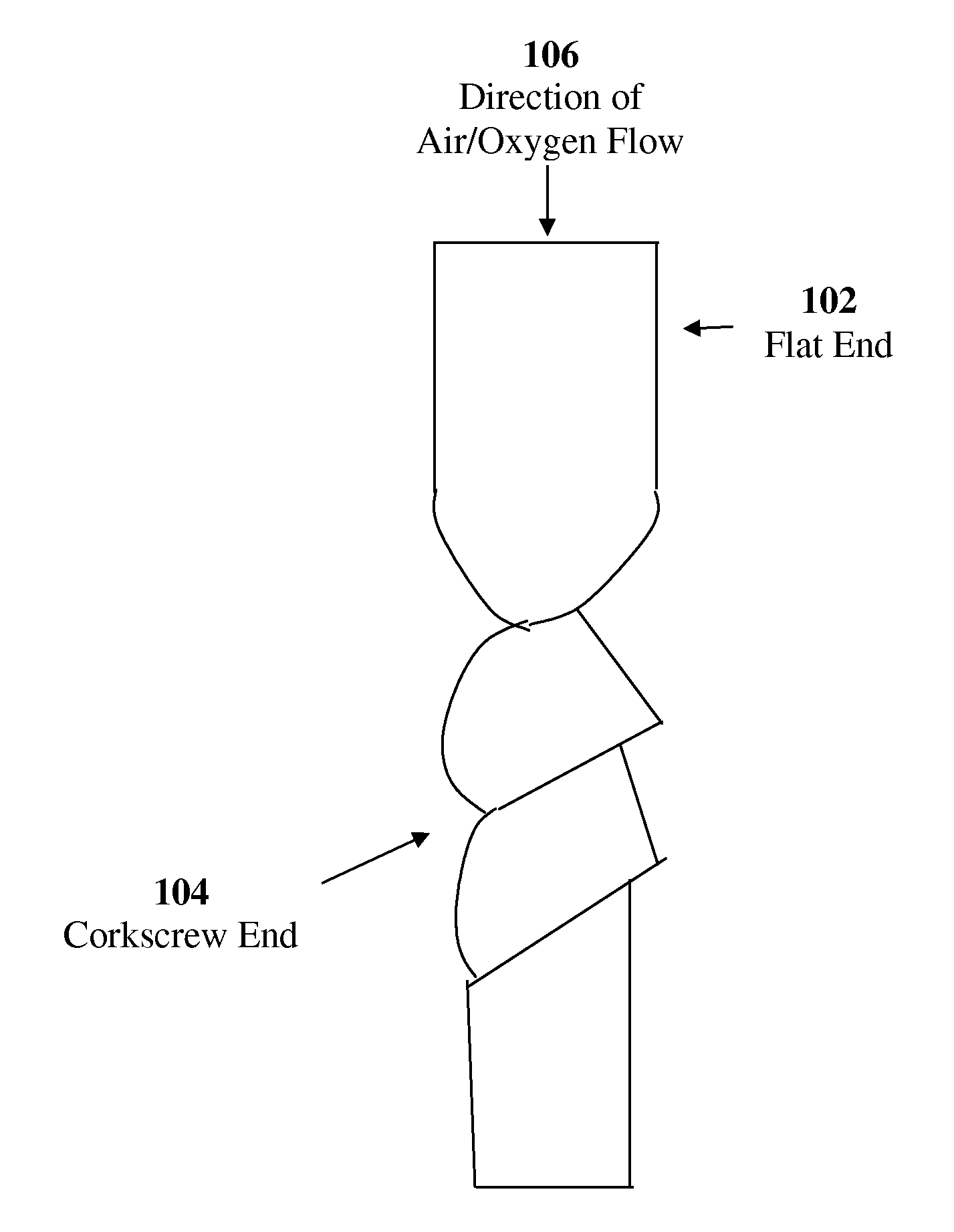
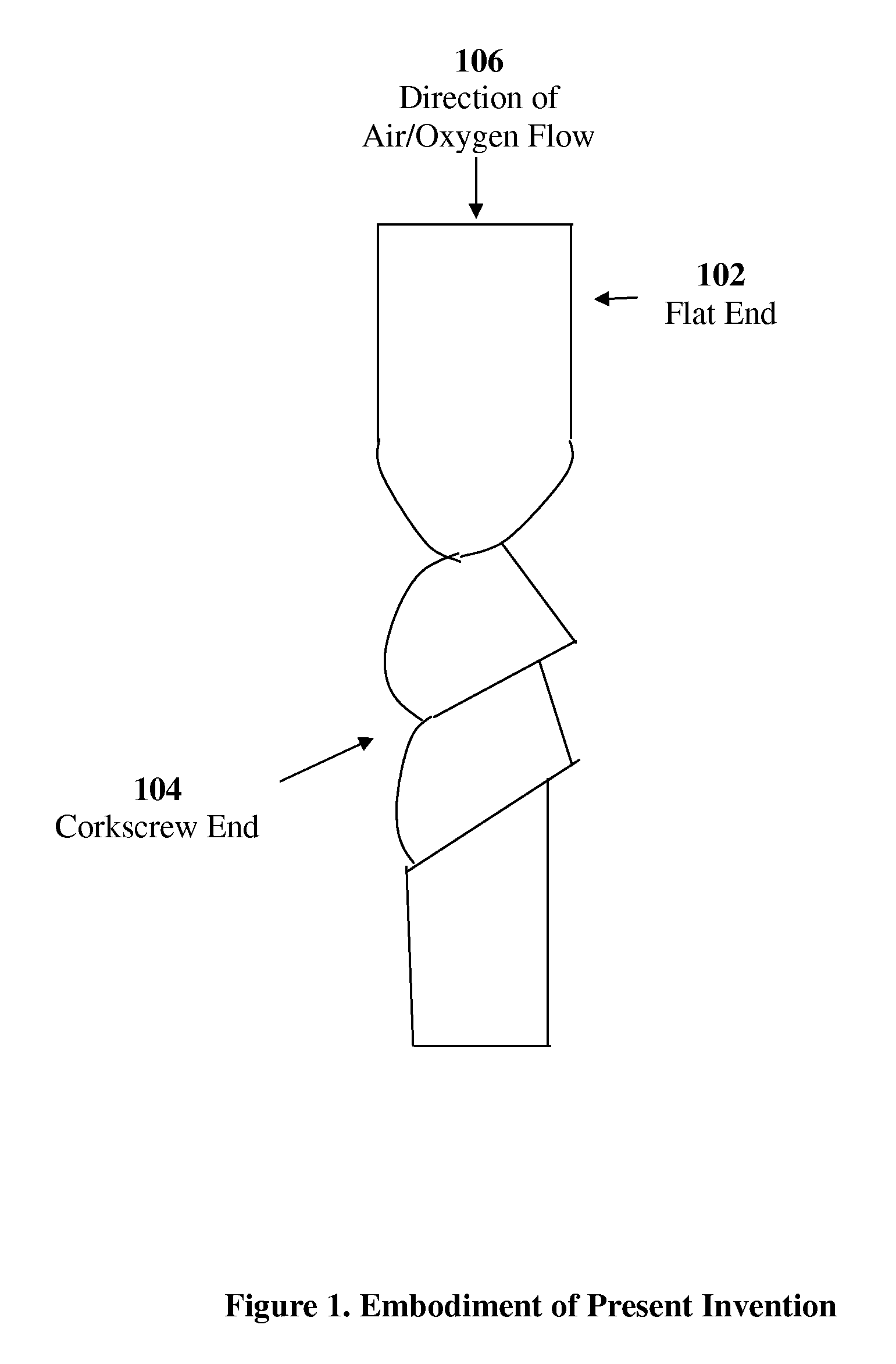
[0016]FIG. 1 illustrates one embodiment of the present invention. In this embodiment, the present invention is a metallic piece that has one flat end 102 and one end 104 that is shaped like a corkscrew. When the present invention is inserted into the center hole of the cutting tip of a cutting / welding torch, the flow of air and oxygen 106 into the cutting tip of the cutting / welding torch is converted into a spinning vortex or “tornado.” The action of the present invention thus concentrates, defines and controls the flow of air and oxygen 106 to the cutting / welding torch, allowing for a more precise cut.

[0017]The inventor's experience in workplace cutting and welding with the present invention indicates that the present invention reduces the amount of oxygen needed to complete a given cutting / welding task by as much as 50%. This reduces the number of oxygen cylinders needed to complete a given cutting / welding task and minimizes total cost of the task.

[0018]The inventor's experience i...


PUM

PropertyMeasurementUnit
Flow rateaaaaaaaaaa

Abstract

Disclosed is a removable device to be inserted into the center hole of the cutting tip of a cutting / welding torch that can be easily cleaned without distorting future cuts, minimizes the amount of oxygen needed for a cutting or welding task, concentrates, controls and defines the flow of air and oxygen into a cutting / welding torch, prevents the center hole of a cutting / welding torch from becoming distorted and imprecise over time, improves the quality of a cut, and minimizes the amount of cut steel that must be cleaned up after a cutting / welding task is completed.

Description

CROSS REFERENCE TO RELATED APPLICATIONS[0001]The present invention claims the benefit of U.S. Provisional Application Ser. No. 61 / 434,128, filed 19 JAN. 2011, entitled “Cutting / Welding Torch Cutting Tip Insert” by Charles Mark Langley.BACKGROUND OF THE INVENTION[0002]a. Field of the Invention[0003]The present invention generally pertains to cutting / welding torches and more particularly to devices that affect the output of cutting / welding torches.[0004]b. Description of the Background[0005]The outer holes of the cutting tip of a cutting / welding torch use a mixture of highly combustible gas (such as acetylene), oxygen and air to create a flame that is high enough to superheat steel. After the steel is superheated, air and oxygen are discharged through the center hole of the cutting tip to blow away the superheated steel and create a cut. Because the oxygen discharged is obtained from pressurized cylinders, it would be economical to minimize the amount of oxygen needed to complete a cu...

Claims


Application Information

Patent Timeline
IPC IPC(8): F15C1/16
CPCB23K7/10B23K5/22Y10T137/0391Y10T137/2087
Inventor LANGLEY, CHARLES MARK
Owner LANGLEY CHARLES MARK
Learn More