Stud welding system, consumables, and method

a technology of consumables and studs, applied in the field of stud welding, can solve the problems of limiting the applicability of studs, unable to use power supplies for other welding purposes, and unable to ensure etc., and achieves the effect of reducing the cost of welding and ensuring the perpendicularity of the underlying surfa

a technology of consumables and studs, applied in the field of stud welding, can solve the problems of limiting the applicability of studs, unable to use power supplies for other welding purposes, and unable to ensure etc., and achieves the effect of reducing the cost of welding and ensuring the perpendicularity of the underlying surfa

US20130015163A1Active Publication Date: 2013-01-17ILLINOIS TOOL WORKS INC

Image

  • Stud welding system, consumables, and method
  • Stud welding system, consumables, and method
  • Stud welding system, consumables, and method

Examples


Embodiment Construction

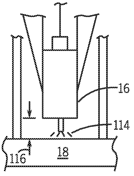
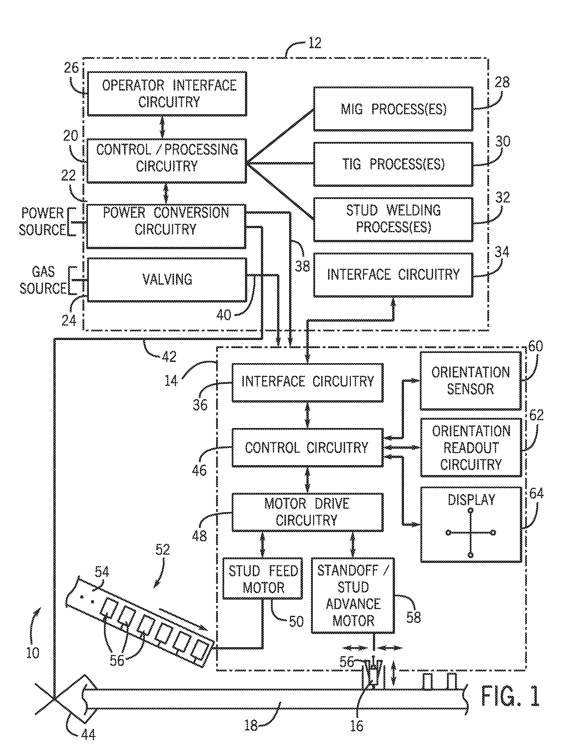
[0015]Turning now to the drawings, FIG. 1 represents an exemplary stud welding system 10 incorporating aspects of the present disclosure. The system includes a welding power supply 12 and a stud welding gun 14 coupled to the power supply, both intended to permit studs 16 to be welded to a workpiece 18. In the illustrated embodiment, the power supply 12 is adapted not only for stud welding but for a range of other welding processes. It comprises control / processing circuitry 20 and power conversion circuitry 22 that cooperate to provide output power in accordance with the selected welding processes. The control / processing circuitry 20 will typically include one or more microprocessors, digital signal processors, or the like and associated memory (not separately represented). The processing circuitry carries out welding processes of generally known types, and may also perform stud welding processes. Under the control of the control / processing circuitry 20, the power conversion circuitr...


PUM

PropertyMeasurementUnit
currentaaaaaaaaaa
currentaaaaaaaaaa
sizesaaaaaaaaaa

Abstract

A stud welding process may be performed by a power supply that is adapted for other welding processes, such as MIG, TIG, and so forth. A stud welding gun may receive studs preloaded in a magazine or other support. Studs are charged into the chuck of a stud welding gun and positioned where desired over a surface. An extension, such as a wire-type electrode may extend from the stud and aid in establishing the welding arc. The stud may be shielded by a nozzle or other shield to obviate the need for ceramic ferrules. Orientation of the stud welding gun may be detected, displayed and used as a basis for initiating and completing the stud welding process once the gun and / or stud is properly positioned.

Description

CROSS REFERENCE TO RELATED APPLICATIONS[0001]This application is a Non-Provisional Patent Application of U.S. Provisional Patent Application No. 61 / 508,431, entitled “Stud Welding System, Consumables, and Method”, filed on Jul. 15, 2011, which is herein incorporated by reference.BACKGROUND[0002]The present invention relates generally to stud welding, and more particularly to a novel stud welding process, new stud welding consumables, and methods for stud welding.[0003]A range of welding operations are known and are currently in use for various specific applications. Among these, stud welding is commonly used to place studs on a mounting surface by application of electric current that fuses the stud to the surface. These techniques are used in a wide range of applications, such as for construction, ship building, and so forth. In many applications great numbers of studs will be placed in this manner for mounting of components to the support surface in subsequent operations. While sig...

Claims


Application Information

Patent Timeline
17 Jan 2013
Publication
US20130015163A1
IPC
B23K9/20; B23K9/095; B23K9/16
CPC
B23K9/1006; B23K9/206; B23K9/20
Inventors
JONES, JERALD EDWARD; RHOADES, VALERIE L.