Microgrid

a micro-grid and grid technology, applied in the direction of transportation and packaging, dc network circuit arrangement, dc source parallel operation, etc., can solve the problems of enlarge what, complex process of grid development, and virtually unknown standard grid designs

Inactive Publication Date: 2013-01-17
INTELLIGENT POWER PARTNERS
View PDF3 Cites 102 Cited by
  • Summary
  • Abstract
  • Description
  • Claims
  • Application Information

AI Technical Summary

Benefits of technology

[0012]In an embodiment, an electric grid comprises a plurality of grid sections; at least one of the grid sections is a microgrid; an edge substation of the microgrid selectively interconnects a substation bus to an electric supply grid or a local generator; for each of a plurality of distribution circuits, a first switch connects one end of the circuit to the bus and a second switch connects another end of the circuit to the bus; for each of

Problems solved by technology

Given that grids are designed and built by utility companies scattered across this and other countries, standardized grid designs are virtually unknown.
Grid

Method used


Image

  • Microgrid
  • Microgrid
  • Microgrid

Examples


Embodiment Construction

[0027]A microgrid is a subsection of the grid that can be separated either temporarily or permanently from the rest of the grid, the grid subsection being configured for interconnection with at least two sources of electric power. Power sources includes one or more of grid feeds from distribution or transmission circuits, generation sources such as solar / photovoltaics or natured gas fired engines, and a combination of local generation and grid feeds.

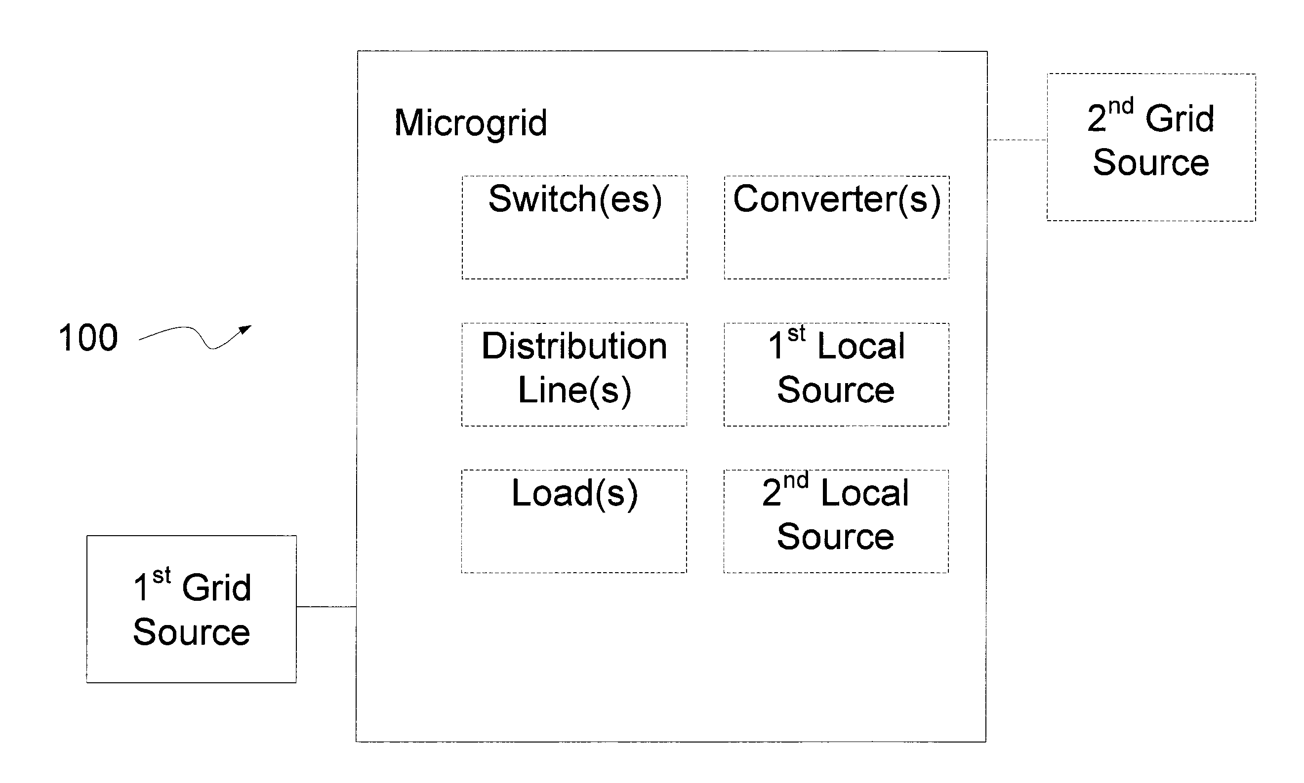
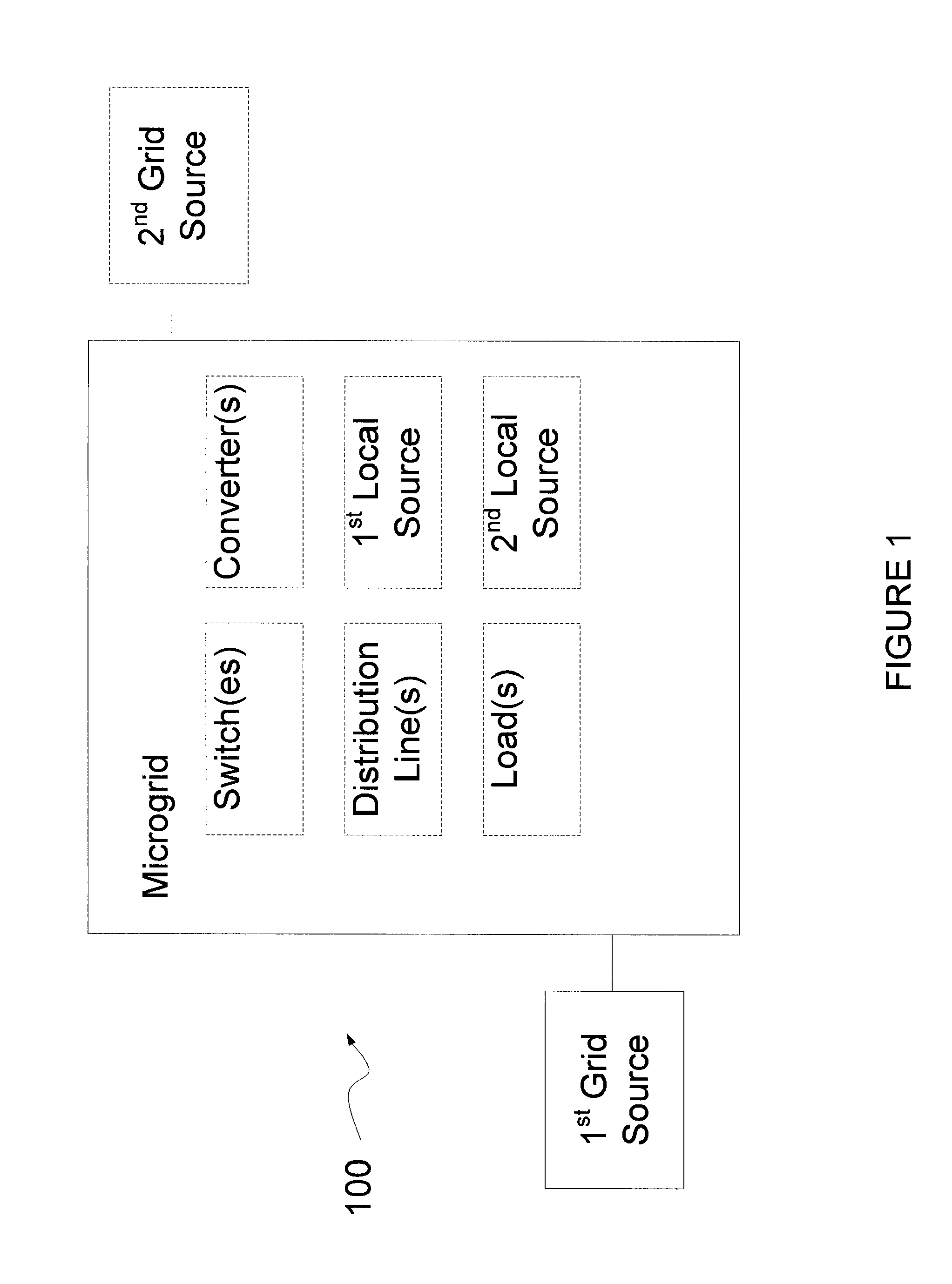
[0028]FIG. 1 illustrates a block diagram of a microgrid 100. The microgrid includes one or more of switches, distribution lines, loads, converters, local power sources, and grid power sources. For example, some microgrids include switches, distribution lines, loads, a Pt external power source and a 2nd external power source. This and other embodiments of microgrids in accordance with the present invention are disclosed below.

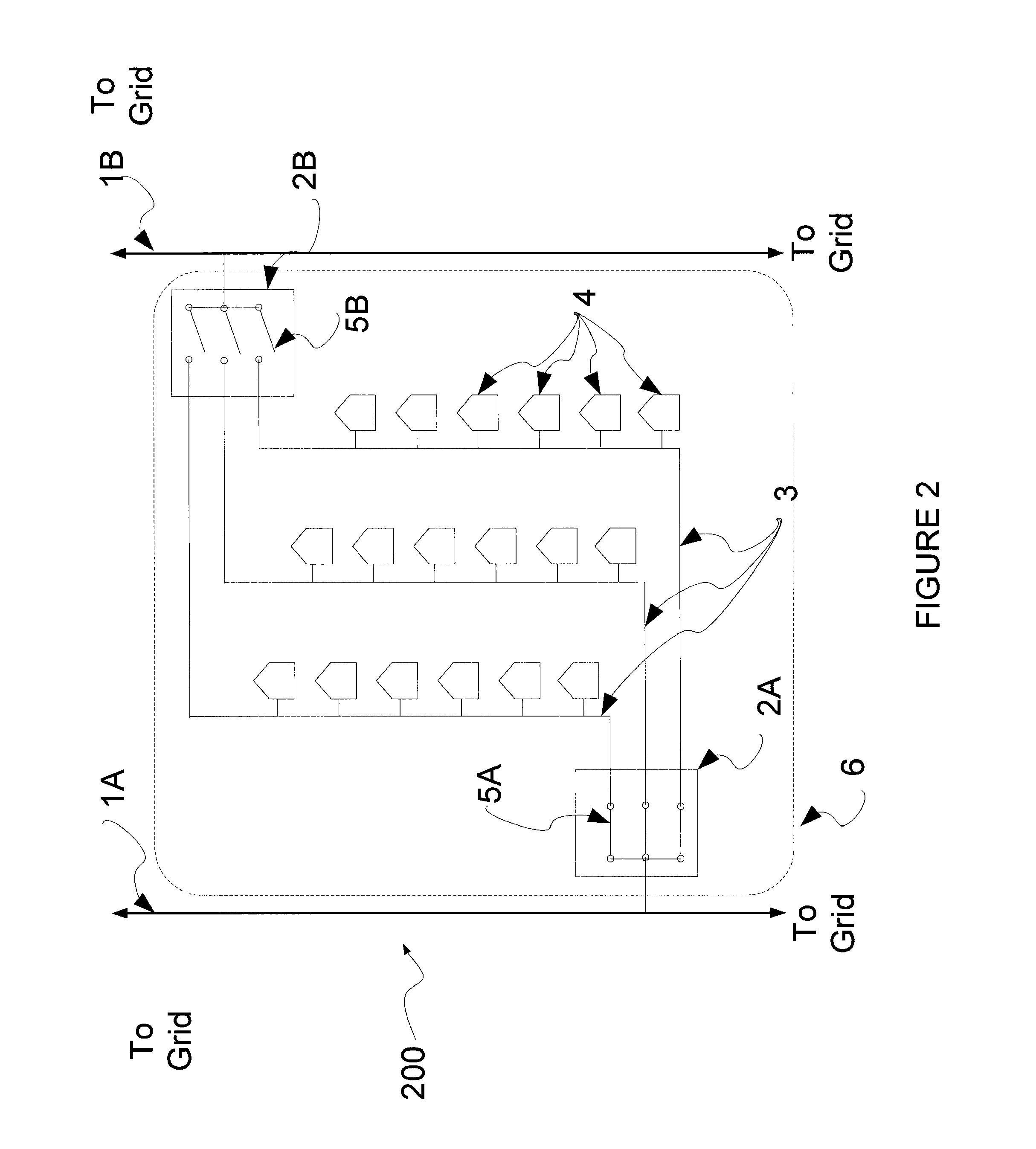
[0029]FIG. 2 illustrates a single line diagram of a first microgrid 200. The single line diagram includes grid fee...


PUM


Abstract

A microgrid is a portion of an electric grid configured for separate management and control as compared with the rest of the grid and having attributes that can be tailored to meet specified needs including the needs of electric power consumers served by the microgrid.

Description

BACKGROUND OF THE INVENTION[0001]1. Field of the Invention[0002]The invention relates to an electrical apparatus. In particular, an electrical grid including a network of electrical conductors is a part of a larger grid.[0003]2. Discussion of the Related Art[0004]One of the earliest electrical grids in the United States was established in 1886 in Detroit when the Edison Illuminating Company began serving its first customers by distributing electricity for street lamps and factories in and around Detroit. Edison was a proponent of direct current electrical generation and distribution but this technology was quickly replaced by alternating current and its ability to be transformed to supply different voltage appliances and to be boosted to recover voltage lost during transmission over long distances.[0005]Modern day electric grids tend to have very high AC transmission voltages for traversing long distances and intermediate AC distribution voltages for supplying power to smaller areas...

Claims


Application Information

Patent Timeline
IPC IPC(8): H02J3/38
CPCH02J3/06H02J3/38
Inventor ROUSE, GREGORY C.KELLY, JOHN F.
Owner INTELLIGENT POWER PARTNERS
Why Eureka
Try Eureka