Systems, Devices, and Methods for Automated Sample Thawing

a technology of automated thawing and sample, applied in the field of cryogenic preservation of cells, can solve the problems of reducing the thaw interval, affecting the thaw rate of samples or samples that have been allowed to become too warm, and affecting the thaw rate, so as to reduce the thaw interval, reduce the damage from ice, and the thaw rate is as rapid

Active Publication Date: 2015-11-19
BIOLIFE SOLUTIONS INC
View PDF7 Cites 24 Cited by
  • Summary
  • Abstract
  • Description
  • Claims
  • Application Information

AI Technical Summary

Benefits of technology

[0031]In further embodiments, another method of thawing a sample within a vessel may be provided. The method may include equilibrating the sample and vessel to an intermediate temperature. The intermediate temperature may be below a sample melting temperature. Thereafter, the sides of the vessel may be contacted with a solid material mass that is maintained at a thawing temperature. The thawing temperature may be greater than 5 degrees above the melting temperature of the sample plus or minus two degrees. A thaw rate that is as rapid as possible may be desired to minimize the damage from ice recrystallization during the thaw process. A reduction in the thaw interval is favored by an increase in the temperature of the vessel receptacle, however as certain vessel shapes such as cylindrical formats may be associated with solid sample thicknesses greater than 1 centimeter in diameter, melting of solid materials contained therein will be accompanied by temperature gradients with a higher temperature at the vessel interior wall, decreasing in magnitude to the solid material remnant temperature toward the center. While liquid sample temperature transients due to temperature gradients incurred by a 37° C. bath thaw of a standard 1.8 ml cryogenic vial do not seem to impact the viability of the majority of established cell lines, the data set is not comprehensive and not reliably applicable to fresh cell isolates and primary cultures, and unfavorable results have been observed for some cryopreservation fluids at temperatures as low as 5° C. Therefore, the optimal thawing rate for a given cell source or viral stock may be case specific, however receptacle temperatures are expected to range from −1° C. to 100° C., typically from 20° C. to 55° C., and in some embodiments, 37° C. to 50° C. A completion of a phase change of the sample contained in the vessel may be predicted by calculating a time interval for a duration of the phase change based on the equilibrating temperature and the heating temperature. A signal may be outputted to interrupt thawing of the sample contained in the vessel at the predicted completion of the phase change of the sample contained in the vessel.

Problems solved by technology

If the sample is allowed to get too warm, the cells may start to metabolize, and be poisoned by the DMSO (dimethyl sulfoxide) that is used in the freezing process.
The completion of sample thaw is generally subjectively judged by each individual technician and may result in variation in the thaw rate or samples which have been allowed to become too warm.
Although a repeatable thawing profile is theoretically possible to achieve using a bath and manual control of the vial insertion, expected variance in both technique and degree of protocol compliance, particularly combined with the requirement to frequently remove the vial from bath to monitor the thaw status, makes deviation from the standard profile a near certainty.
The removal of the vial from the bath interrupts the thermal energy transfer from the bath water to the vial and visual assessment of the thaw status is often difficult and may be complicated by the presence of vial labels and printed writing surfaces that are provided as integrated features of the vial product.
Further water baths are also a source of contamination and inadvertent submersion of the vial body-cap junction can result in the introduction of bath liquid into the vial contents during removal of the vial cap.

Method used


Image

  • Systems, Devices, and Methods for Automated Sample Thawing
  • Systems, Devices, and Methods for Automated Sample Thawing
  • Systems, Devices, and Methods for Automated Sample Thawing

Examples


Embodiment Construction

[0064]The subject matter of embodiments of the present invention is described here with specificity, but this description is not necessarily intended to limit the scope of the claims. The claimed subject matter may be embodied in other ways, may include different elements or steps, and may be used in conjunction with other existing or future technologies. This description should not be interpreted as implying any particular order or arrangement among or between various steps or elements except when the order of individual steps or arrangement of elements is explicitly described.

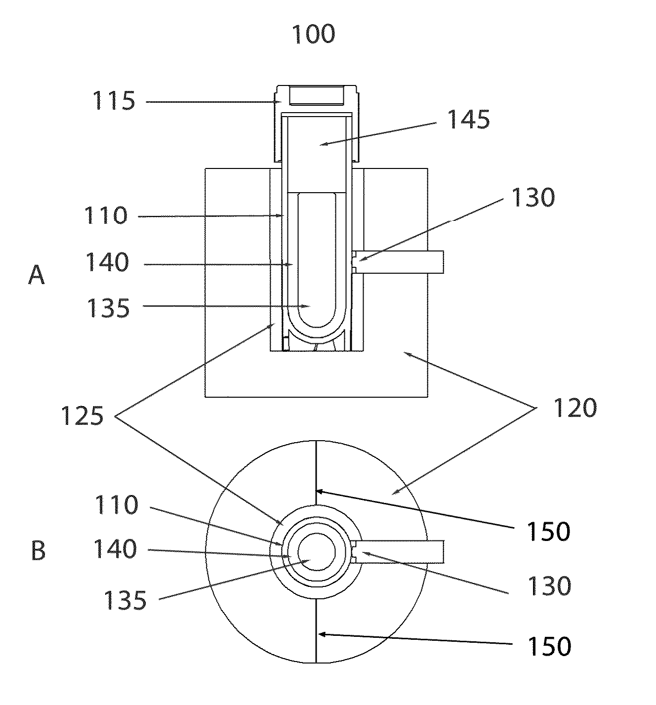
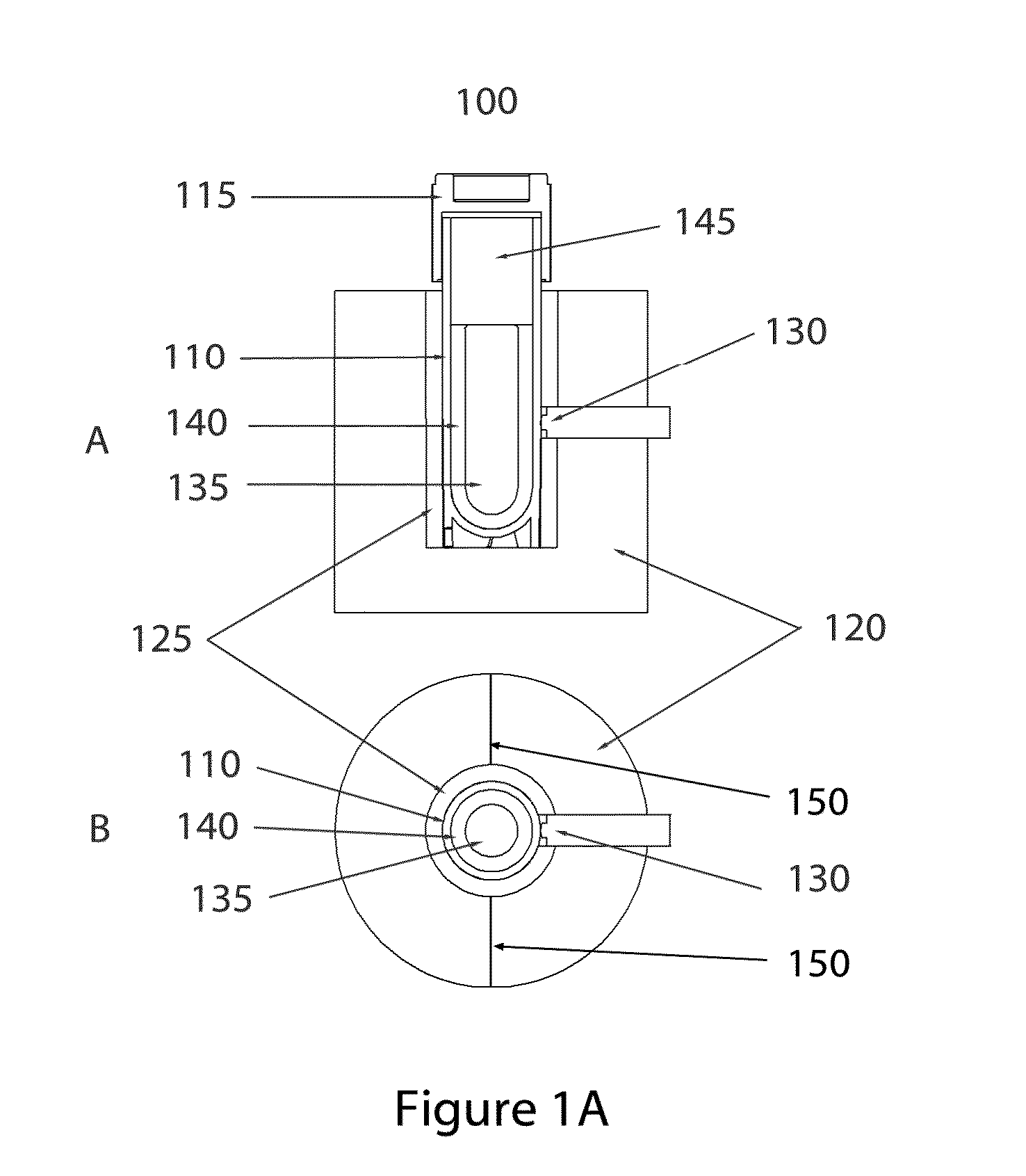
[0065]In some embodiments of the invention, direct liquid contact with the sample vial exterior may be eliminated, as would occur with a partial submersion of the sample in a water bath. As such, in many embodiments of the invention the exterior surface of the sample vial, or in some cases the sample vial exterior plus laminations such as labels or shrink-wrap sleeves, will be in contact only with solid mater...


PUM

PropertyMeasurementUnit
temperatureaaaaaaaaaa
temperaturesaaaaaaaaaa

Abstract

The present invention generally relates to thawing a cryogenically frozen sample. The systems, devices, and methods may be used to heat a sample holder, the sample holder configured to receive a sample container holding the frozen sample. A sample thaw start time may be identified by measuring a temperature of the sample container and/or a temperature of the sample. A sample thaw end time may be calculated as a function of the sample thaw start time. In some embodiments, the same thaw start time may be identified by a significant change in a first derivative of a warming curve of recorded temperature measurements. The sample end time may be calculated by adding a constant to the sample thaw start time. The constant may be the average sample thaw time per the sample container.

Description

CROSS-REFERENCE TO RELATED APPLICATIONS[0001]The present application claims priority to U.S. Provisional Application No. 61 / 994,586 filed May 16, 2014 and U.S. Provisional Application No. 62 / 042,669 filed Aug. 27, 2014, the full disclosures which are incorporated herein by reference in their entirety for all purposes.BACKGROUND OF THE INVENTION[0002]The present invention generally relates to the cryogenic preservation of cells and more specifically to systems, devices, and methods for the recovery of cryogenically-preserved cells and tissue.[0003]Cryogenic preservation of cells in suspension is a well-established and accepted technique for long term archival storage and recovery of live cells. As a general method, cells are suspended in a cryopreservation media typically including salt solutions, buffers, nutrients, growth factors, proteins, and cryopreservatives. The cells are then distributed to archival storage containers of the desired size and volume, and the containers are the...

Claims


Application Information

Patent Timeline
Patent Type & Authority Applications(United States)
IPC IPC(8): H05B1/02G01K7/22B01L7/00G01K3/10G01K7/02
CPCH05B1/025B01L7/00G01K7/22G01K3/10A47J36/24A47J36/2483A47J36/32A01N1/0252A01N1/0284
Inventor SCHRYVER, BRIANSHANNON, DAVID
Owner BIOLIFE SOLUTIONS INC
Why Eureka
Try Eureka