Failure detection system for photovoltaic array

a photovoltaic array and fault detection technology, applied in photovoltaic monitoring, measurement devices, instruments, etc., can solve the problems of inexhaustible source or electrical power, limited traditional fossil fuel generation, constant price fluctuation, etc., and achieve the effect of preventing current backfeeding

Inactive Publication Date: 2013-01-17
UNITED SOLAR OVONIC
View PDF6 Cites 45 Cited by
  • Summary
  • Abstract
  • Description
  • Claims
  • Application Information

AI Technical Summary

Benefits of technology

[0013]In some embodiments, a switch is a field effect transistor. The switch is optionally located at the negative terminus of the string. To further prevent backfeeding of current to a fault, one or more strings optionally includes a reverse flow preventative diode that is optionally located proximal to the positive terminus of the string.

Problems solved by technology

Traditional fossil fuel generation is limited by supply issues and is constantly subject to price fluctuations due to market conditions.
Solar energy represents a plentiful and virtually inexhaustible source or electrical power.
These locations are commonly also exposed to thermal differences and are at risk of impacts from the surrounding environment.
These perils increase the risk of physical decay that could lead to electrical faults in the arrays.
Compromised laminate insulation or broken leads, under certain conditions, can result in exposed DC voltage of a few hundred volts with respect to the grounded substrate.
This exposed source of electric energy can combine with water from dew / rain or debris collected near the array to create a dangerous electric arc.
This system has many drawbacks including that the system is limited to detection of ground faults leaving other types of fault either undetected or uncorrected.
Additionally, the faulty substring will continue to remain fully powered as long as it is exposed to sufficient light energy such that the fault will continue unabated until a user intervenes.
This does not adequately prevent physical damage that may result from the fault.
Thus, this system suffers from poor ability to quickly and effectively detect faults such as arc faults and effectively prevent possible damage resulting from the fault.
The prior systems are incapable of effectively detecting multiple fault types with the speed and sensitivity necessary for effective control of fault induced damage, and to simultaneously allow a photovoltaic array to continue to function should a fault be present in a portion of the system.

Method used


Image

  • Failure detection system for photovoltaic array
  • Failure detection system for photovoltaic array
  • Failure detection system for photovoltaic array

Examples


Embodiment Construction

[0017]The following description of particular embodiment(s) is merely exemplary in nature and is in no way intended to limit the scope of the invention, its application, or uses, which may, of course, vary. The invention is described with relation to the non-limiting definitions and terminology included herein. These definitions and terminology are not designed to function as a limitation on the scope or practice of the invention but are presented for illustrative and descriptive purposes only.

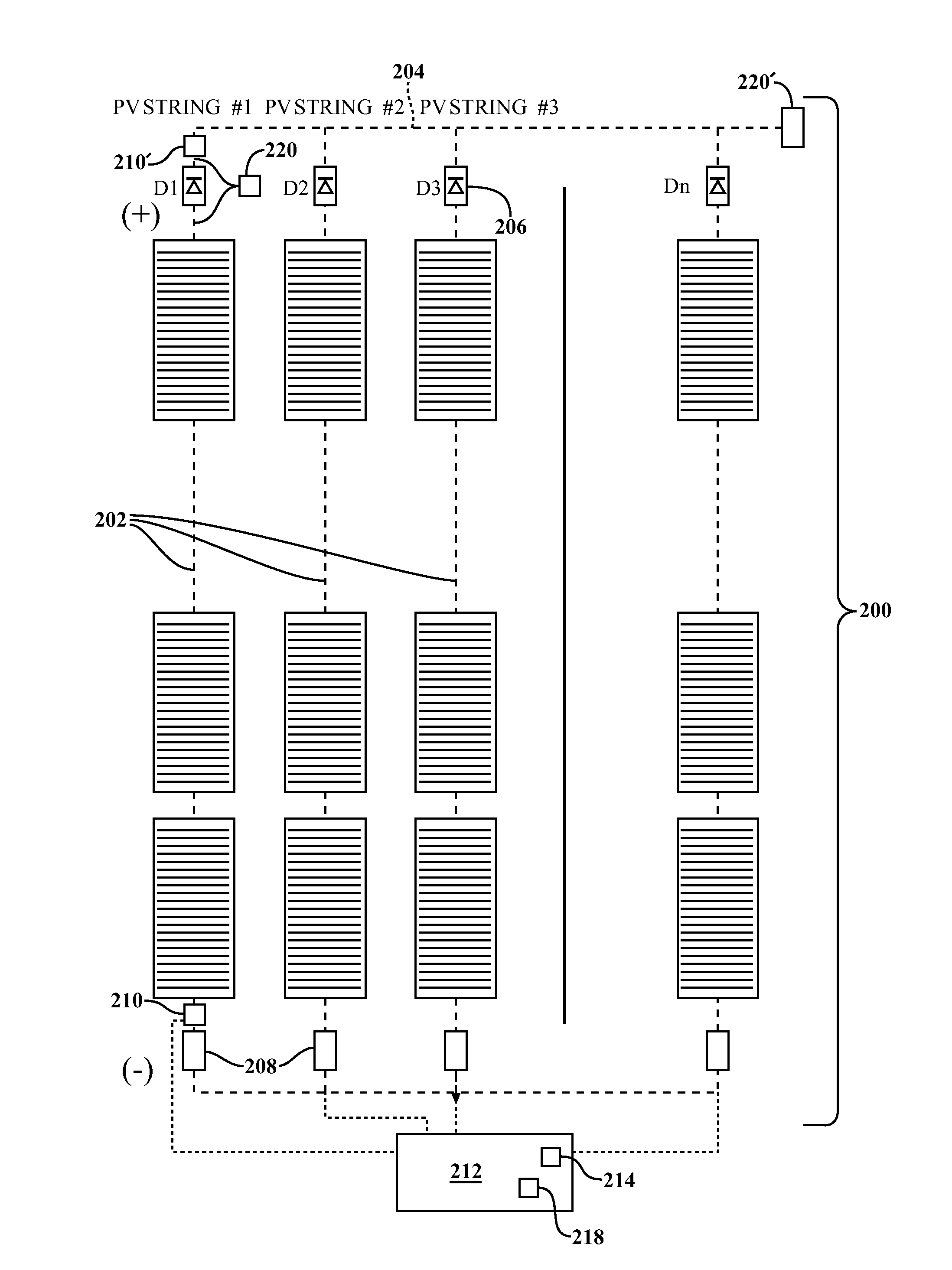
[0018]The invention has utility as a process and system for the detection, isolation, and suppression of a fault in a photovoltaic string. The processes and systems provide rapid and sensitive, yet reliable detection of a fault such as a ground fault or an arc fault. The process detects a fault within one or more of a plurality of strings where a string includes one or more photovoltaic cells connected in series.

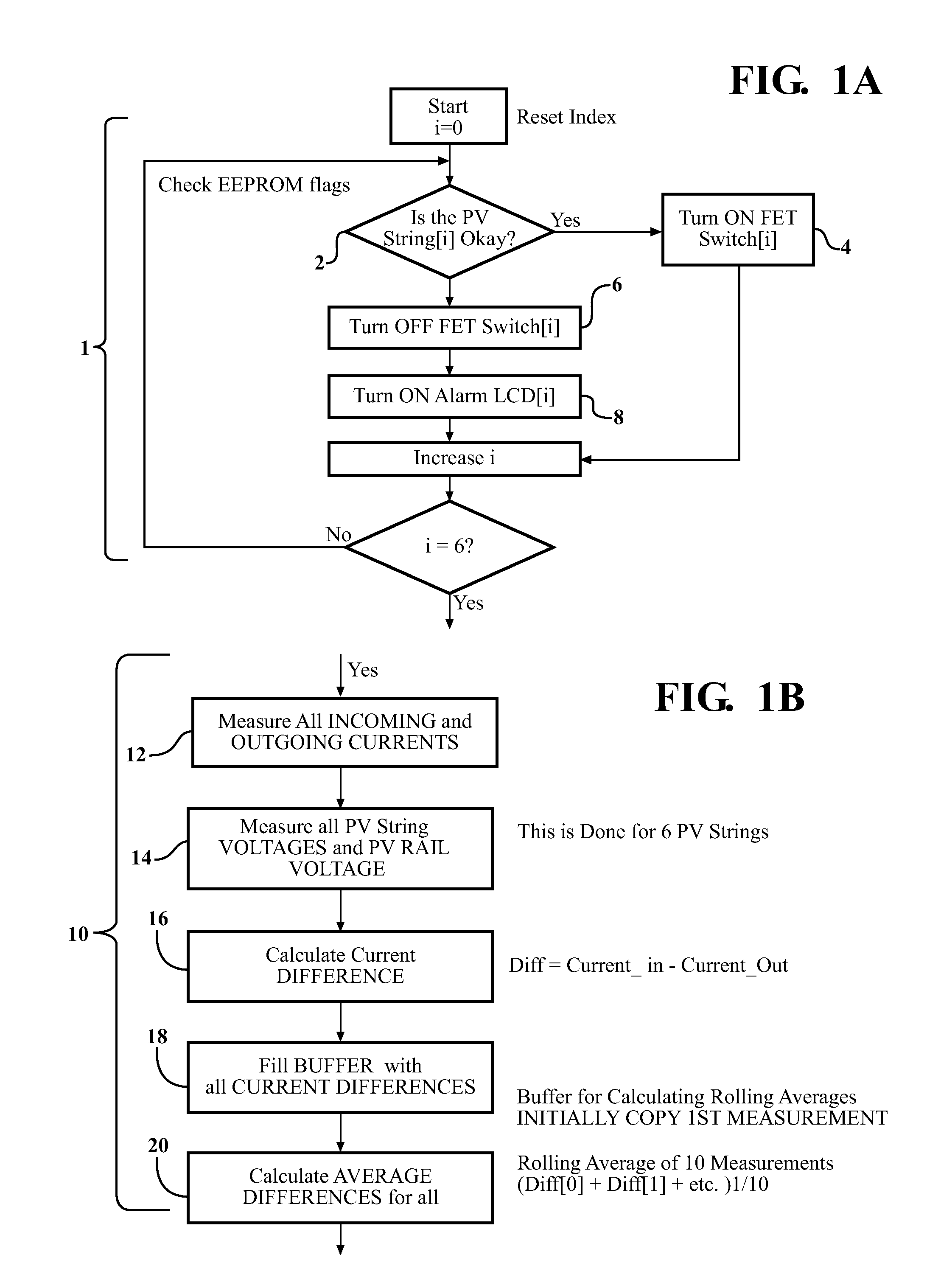
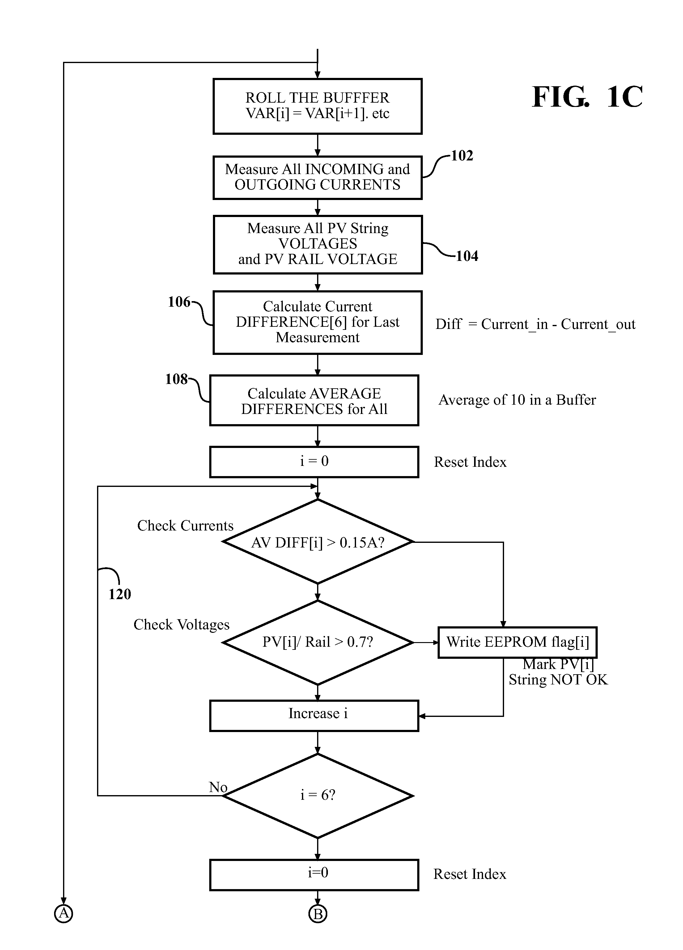
[0019]A process includes detecting one or more differences in an electrical parame...


PUM


Abstract

A process for detecting and terminating a fault in a photovoltaic device is provided that operates in the millisecond or faster timescale. A process includes measuring a current or voltage in each of a plurality of strings relative to a common rail. When the voltage or current from a string is outside a predetermined threshold, a flag is generated indicating the presence of a fault in the string. A control unit will detect the flag and disconnect the faulty string from the system through a switch. The use of continuously rolling averages of baseline currents and voltages as well as a series of measurements averaged to measure the difference of current or voltage at each step provides a process and a fault detection system that does not suffer from false fault detections thereby providing a reliable and efficient system for detecting and terminating faults in photovoltaic devices.

Description

FIELD OF THE INVENTION[0001]The invention is related to fault detection in photovoltaic devices. More specifically, the invention is related to arc or other fault detection and suppression of subsequent thermal events relating to a defective photovoltaic device string.BACKGROUND OF THE INVENTION[0002]Demand for electrical energy continues to rise due to the introduction of new electrical devices and increased use of climate control systems. Traditional fossil fuel generation is limited by supply issues and is constantly subject to price fluctuations due to market conditions. Alternative energy sources are, therefore, in expanding demand. Solar energy represents a plentiful and virtually inexhaustible source or electrical power. There is great desire for improved solar generation devices useful for household and industrial solar electricity generation.[0003]Photovoltaic arrays made of strings of photovoltaic cells must be supported by a high degree of safety. Of equal importance is m...

Claims


Application Information

Patent Timeline
Patent Type & Authority Applications(United States)
IPC IPC(8): G01R31/26
CPCH02S50/10Y02E10/50
Inventor KUMAR, ARUN
Owner UNITED SOLAR OVONIC
Why Eureka
Try Eureka