
Trace shielding for input devices

a shielding and input device technology, applied in the direction of instruments, printed circuits, computing, etc., can solve the problems of undesired interference between routing traces and sensing components, and achieve the effect of reducing the effect of input objects, reducing capacitive coupling, and reducing capacitive coupling

Active Publication Date: 2013-01-17
SYNAPTICS INC
View PDF4 Cites 78 Cited by
  • Summary
  • Abstract
  • Description
  • Claims
  • Application Information

AI Technical Summary

Benefits of technology

The present invention provides a system for capacitive sensing in a display device that reduces the impact of input objects and other factors on the capacitive coupling between conductive routing traces and receiver electrodes. This is achieved by shielding the conductive routing traces from the receiver electrodes in a way that reduces the effect of the input object on the coupling. The system includes a plurality of common electrodes for display updating and capacitive sensing, and a plurality of conductive routing traces coupled to the common electrodes. A driver module is coupled to the conductive routing traces to drive transmitter signals onto the common electrodes, and a plurality of receiver electrodes is shielded from the conductive routing traces in a way that reduces the impact of input objects. The system also includes a receiver module to receive the resulting signals with the receiver electrodes.

Problems solved by technology

In addition, as device thickness decreases, the distance between the routing traces, through which signals are transmitted to the common transmitter electrodes, and the sensing components, such as the receiver electrodes, is decreased, resulting in undesired interference between the routing traces and the sensing components, especially when an input object approaches the sensing region of the input device.

Method used


Image

  • Trace shielding for input devices
  • Trace shielding for input devices
  • Trace shielding for input devices

Examples


Embodiment Construction

[0030]The following detailed description is merely exemplary in nature and is not intended to limit the invention or the application and uses of the invention. Furthermore, there is no intention to be bound by any expressed or implied theory presented in the preceding technical field, background, brief summary or the following detailed description.

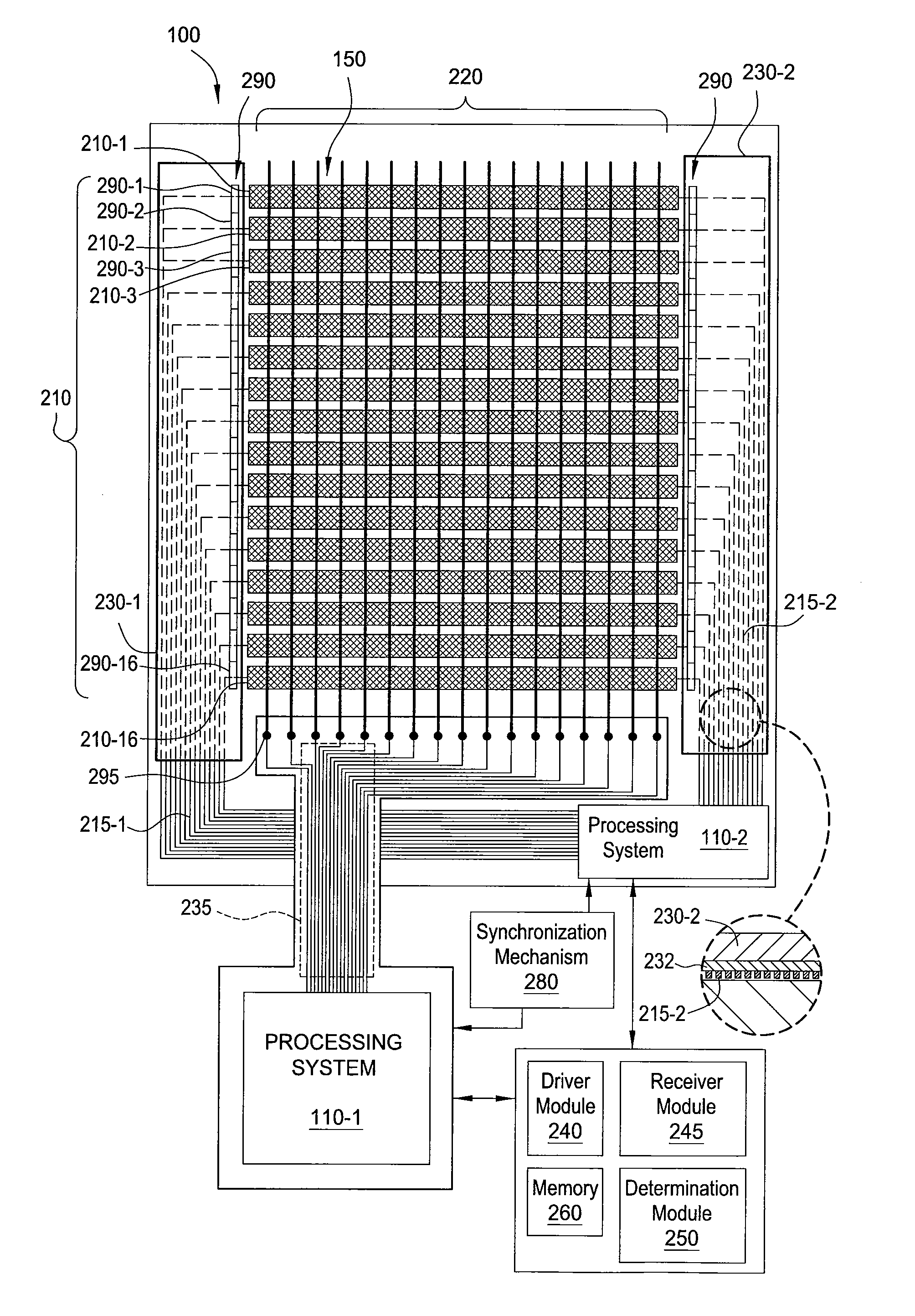
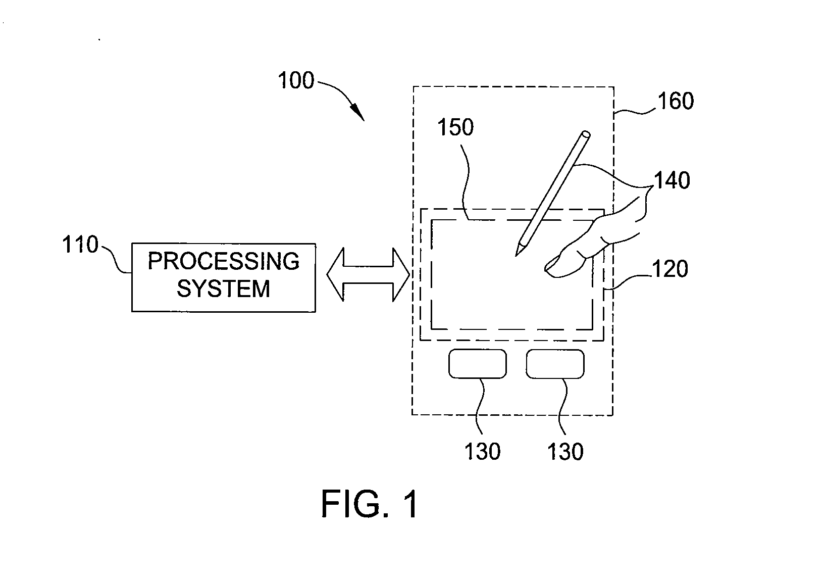
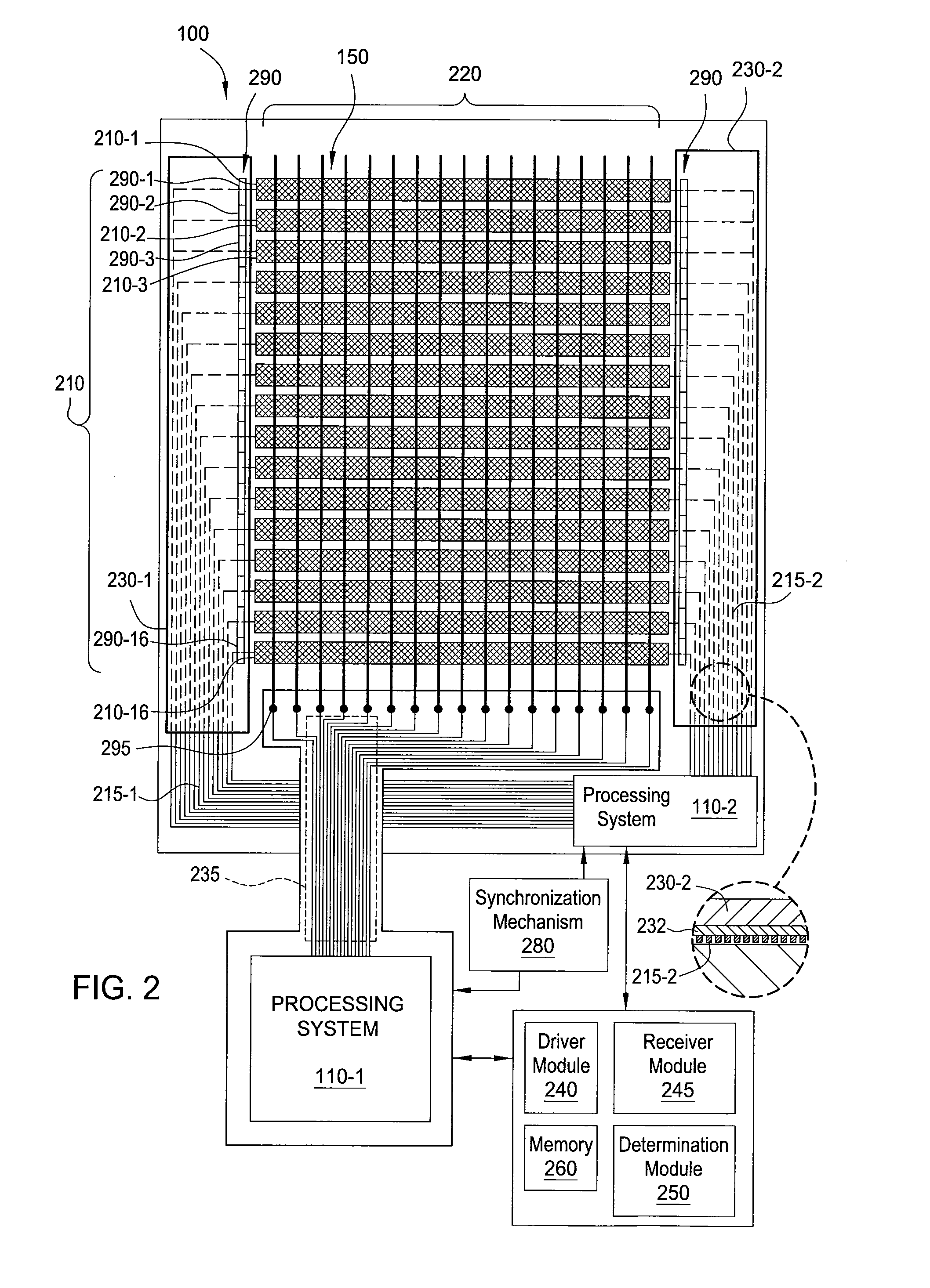
[0031]Various embodiments of the present invention generally provide shield electrodes for shielding one or more conductive routing traces from one or more receiver electrodes in an input device comprising a display device integrated with a sensing device to reduce the capacitive coupling between the conductive routing traces and the receiver electrodes. The shield electrode may be configured to reduce the effect of an input object on the capacitive coupling between the conductive routing traces and the receiver electrodes. In other embodiments, end portions of common electrodes shield the receiver electrodes from the conductive routing tr...


PUM


Abstract

Embodiments of the present invention generally provide shield electrodes for shielding one or more conductive routing traces from one or more receiver electrodes in an input device comprising a display device integrated with a sensing device to reduce the capacitive coupling between the conductive routing traces and the receiver electrodes. The shield electrode may be configured to reduce the effect of an input object on the capacitive coupling between the conductive routing traces and the receiver electrodes. In other embodiments, end portions of common electrodes shield the receiver electrodes from the conductive routing traces, thereby reducing the capacitive coupling between the receiver electrodes and the conductive routing traces.

Description

CROSS-REFERENCE TO RELATED APPLICATIONS[0001]This application claims benefit of U.S. Provisional Patent Application Ser. No. 61 / 507,369, filed Jul. 13, 2011, which is herein incorporated by reference in its entirety.BACKGROUND OF THE INVENTION[0002]1. Field of the Invention[0003]Embodiments of the present invention generally relate to a system and device for improving the interference performance of an input device integrated with a display device.[0004]2. Description of the Related Art[0005]Input devices including proximity sensor devices (also commonly called touchpads or touch sensor devices) are widely used in a variety of electronic systems. A proximity sensor device typically includes a sensing region, often demarked by a surface, in which the proximity sensor device determines the presence, location, and / or motion of one or more input objects. Proximity sensor devices may be used to provide interfaces for the electronic system. For example, proximity sensor devices are often ...

Claims


Application Information

Patent Timeline
Patent Type & Authority Applications(United States)
IPC IPC(8): G06F3/044
CPCG06F3/0412G06F2203/04107G06F3/044G06F3/0443G06F3/047G09G2300/0426H05K1/0306H05K1/115H05K2201/10151
Inventor REYNOLDS, JOSEPH KURTHSHEPELEV, PETR
Owner SYNAPTICS INC
Features
  • Generate Ideas
  • Intellectual Property
  • Life Sciences
  • Materials
  • Tech Scout
  • Unparalleled Data Quality
  • Higher Quality Content
  • 60% Fewer Hallucinations
Learn More