Imaging apparatus

a technology of af evaluation value and an imager, which is applied in the field of imaging apparatus, can solve the problems of difficult to detect the focal point from the probability of not being able to focus on the subject, and the peak position of the af evaluation value is mistakenly detected

Inactive Publication Date: 2013-01-17
SANYO ELECTRIC CO LTD
View PDF3 Cites 68 Cited by
  • Summary
  • Abstract
  • Description
  • Claims
  • Application Information

AI Technical Summary

Problems solved by technology

This is to avoid a situation where when the cutoff frequency of the HPF is too high, most of the frequency components of the luminance signal are blocked by the HPF, and as a result, it is difficult to detect the focal point from the AF evaluation value.
This is to avoid a situation where if the cutoff frequency of the HPF is too low, most of the frequency components of the luminance signal pass through the HPF, which results in a mistaken detection of the peak position of the AF evaluation value.
Thus, when the subject of a low contrast, together with the subject including the point light source, is included in the focus area, it is not possible to obtain a sufficient high-range frequency component of the luminance signal from the image signal in a region in which the subject of a low contrast is included, and as a result, an absolute amount of the AF evaluation value is small, resulting in a probability of not being able to focus on the subject.

Method used


Image

  • Imaging apparatus
  • Imaging apparatus
  • Imaging apparatus

Examples


Embodiment Construction

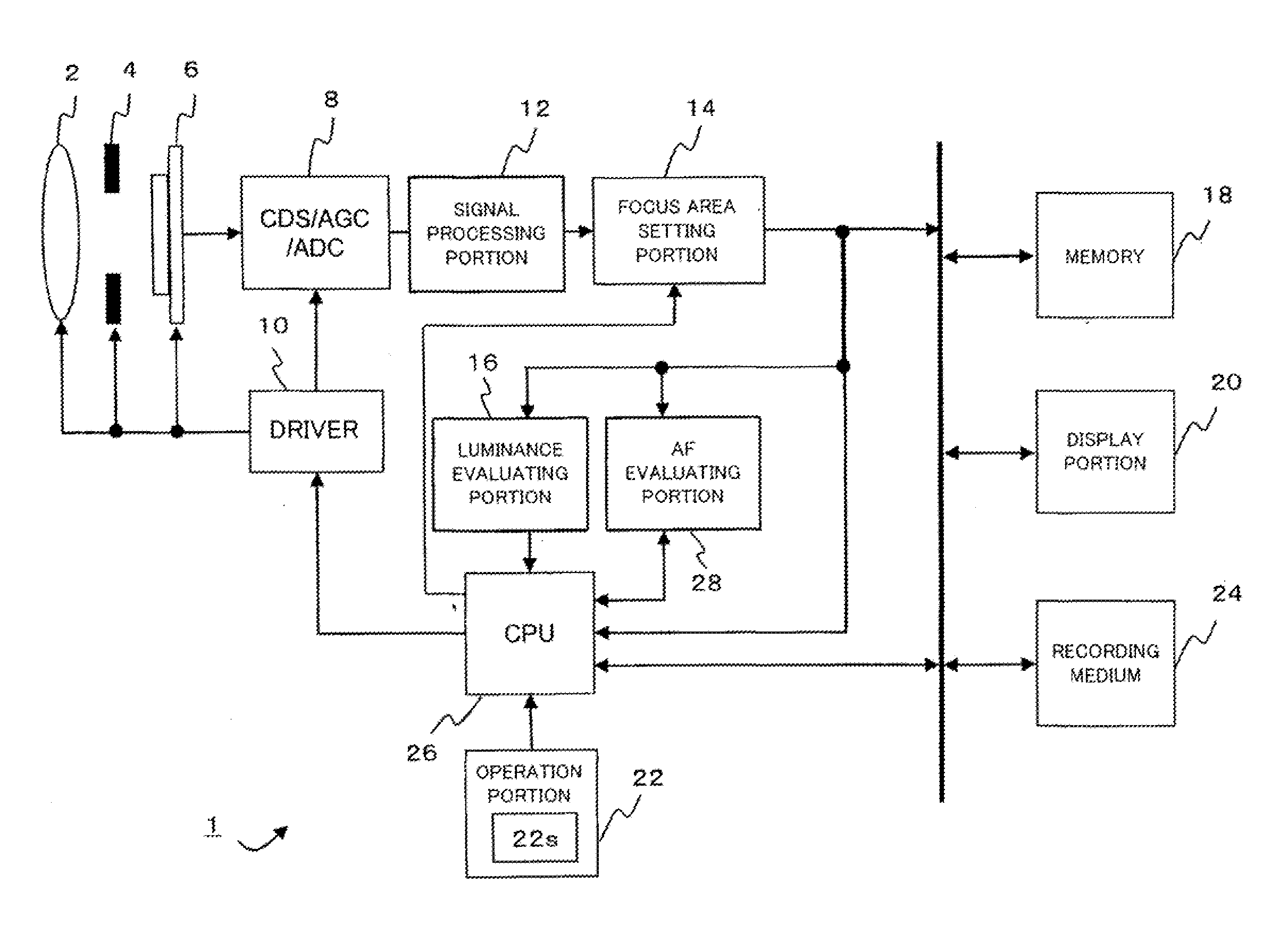
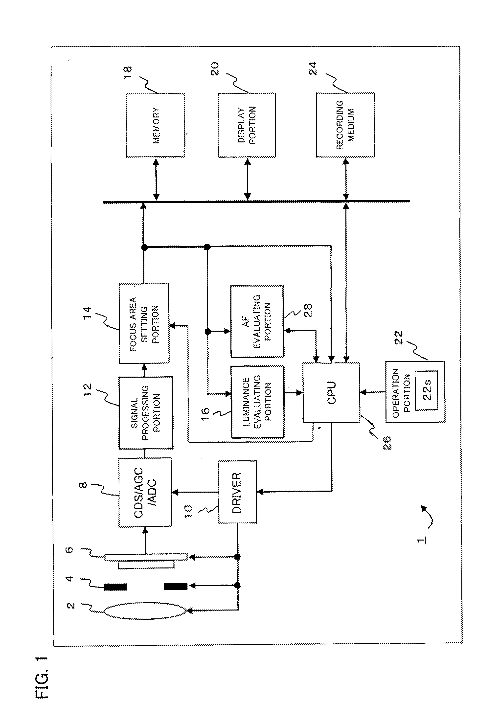
[0027]One embodiment of the present invention is described with reference to the drawings. FIG. 1 is a block diagram showing an overview of a configuration of an imaging apparatus 1 according to the present invention. The imaging apparatus 1 is provided with a focus lens 2 for focusing on a subject, an aperture 4 which adjusts an exposure amount, and an imaging element 6 which performs photoelectric conversion on an optical image of the subject to obtain an image signal, and includes a CDS / AGC / ADC 8 configured by a CDS (Correlated Double Sampling) which performs a correlated double sampling process on the image signal converted by the imaging element 6, an AGC (Automatic Gain Control) which performs automatic gain control on the same, and an ADC (Analog Digital Conversion) which performs an A / D conversion on the same. Furthermore, the imaging apparatus 1 is provided with a driver 10 which controls the focus lens 2, the aperture 4, the imaging element 6, and the CDS / AGC / ADC 8, and a ...


PUM


Abstract

An imaging apparatus includes an imager which acquires an image signal of a subject. A first filter processer performs a filer process on a luminance signal included in the image signal in a focus area. A second filter processor performs a filter process on the luminance signal included in the image signal in the focus area and to which a cutoff frequency different from the cutoff frequency of the first filter processor is set. A first determiner determines whether or not a point light source is included in the subject. A calculator calculates an evaluation value from the luminance signal included in the image signal in the focus area. A focuser performs focus control based on the evaluation value. When it is determined that the point light source is included in the subject, the calculator calculates the evaluation value based on outputs of the first and second filter processor.

Description

CROSS REFERENCE OF RELATED APPLICATION[0001]The disclosure of Japanese Patent Application No. 2011-156012, which was filed on Jul. 14, 2011, is incorporated herein by reference.BACKGROUND OF THE INVENTION[0002]1. Field of the Invention[0003]The present invention relates to an imaging apparatus, and more specifically, the present invention relates to an imaging apparatus which adjusts a focus position of an optical lens by an AF (Automatic Focus) process.[0004]2. Description of the Related Art[0005]One of the methods for AF control includes hill-climbing AF control (also referred to as contrast AF control). In the hill-climbing AF control, a luminance signal (Y signal) included in an image signal passes through an HPF (High-Pass Filter) thereby to detect a high-range frequency component of the luminance signal so that an integrated value (hereinafter, described as AF evaluation value) of the high-range frequency component of the luminance signal is calculated.[0006]A focus lens posit...

Claims


Application Information

Patent Timeline
Patent Type & Authority Applications(United States)
IPC IPC(8): H04N5/232H04N5/225
CPCH04N5/23212G03B13/36H04N23/673
Inventor YUBA, MOTOHIRO
Owner SANYO ELECTRIC CO LTD
Why Eureka
Try Eureka