Image capturing lens system

a technology of image capturing and lens system, which is applied in the field of image capturing lens system, can solve the problems of inability to produce high-quality images, insufficient degree of freedom in setting system parameters, and the length of the total optical track of the lens structur

Active Publication Date: 2013-01-17
LARGAN PRECISION
View PDF1 Cites 6 Cited by
  • Summary
  • Abstract
  • Description
  • Claims
  • Application Information

AI Technical Summary

Benefits of technology

[0035]When a focal length of the image capturing lens system is f, a curvature radius of the image-side surface of the third lens element is R6, and a curvature radius of the object-side surface of the fourth lens element is R7, the following relationship is satisfied:
[0013]FIG. 3 is a schematic view of an image capturing lens system according to the second lens embodiment of the present disclosure;
[0030]An image capturing lens system includes, in order from an object side to an image side, a first lens element, a second lens element, a third lens element and a fourth lens element. From the first lens element to the fourth lens element are four non-cemented lens elements. That is, any two lens elements adjacent to each other are not cemented, and there is an air space between the two lens elements. The manufacture of the cemented lenses is more complex than the manufacture of the non-cemented lenses. Especially, the cemented surfaces of the two lens elements should have accurate curvatures for ensuring the connection between the two lens elements, and the displacement between the cemented surfaces of the two lens elements during cementing the lens elements may affect the optical quality of the image capturing lens system. Therefore, the image capturing lens system of the present disclosure provides fourth non-cemented lens elements for improving the problem generated by the cemented lens elements.

Problems solved by technology

While the three-element lens structure is compact, it is not able to produce high quality images.
However, this lens structure requires a longer total optical track length caused by insufficient degrees of freedom in setting system parameters due to too many spherical lenses allocated.
Moreover, it is not easy to attach the glass lenses, and thus the manufacturing process for forming the glass doublet lenses is difficult.

Method used


Image

  • Image capturing lens system
  • Image capturing lens system
  • Image capturing lens system

Examples


first embodiment

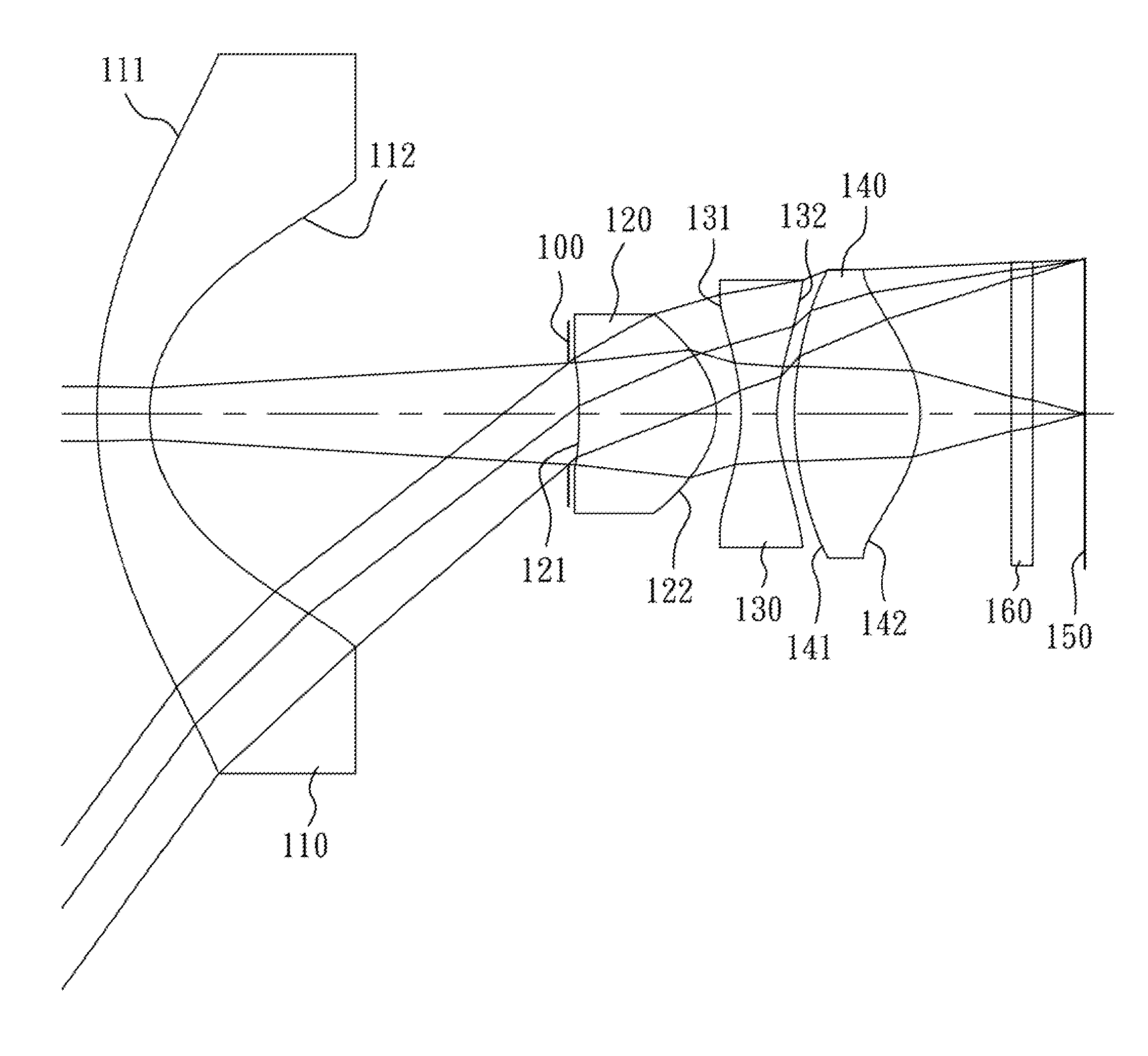
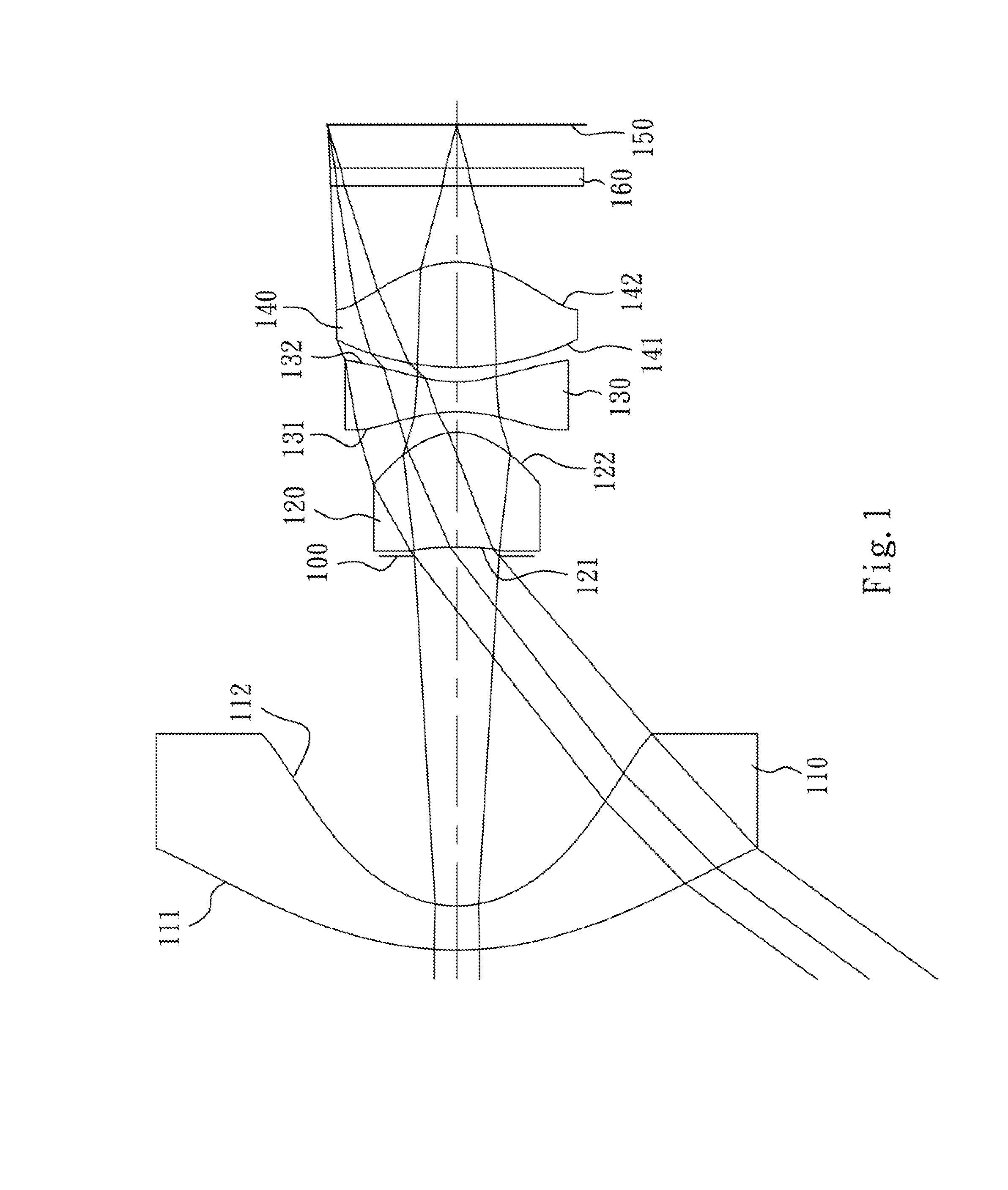
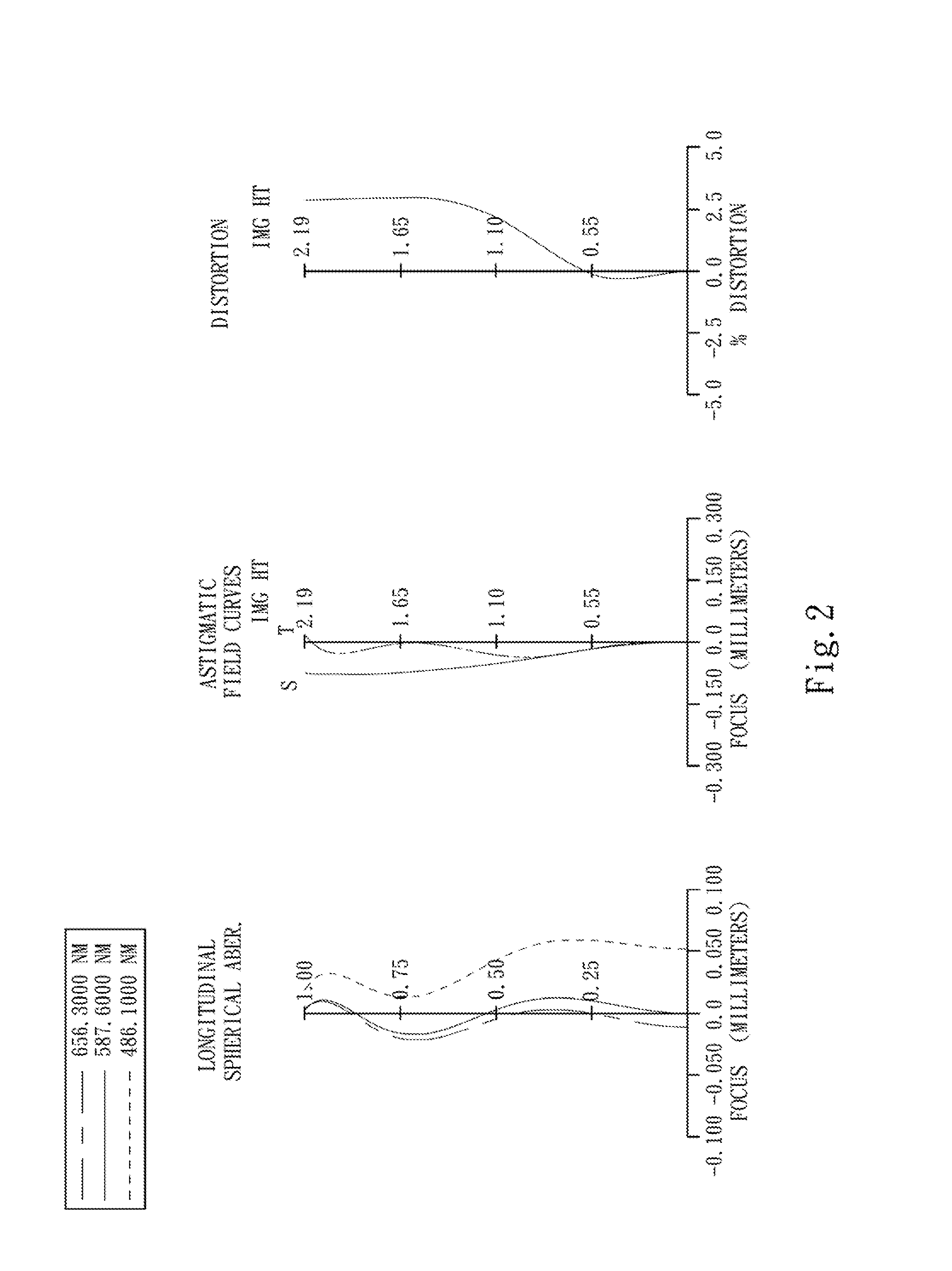
[0060]FIG. 1 is a schematic view of an image capturing lens system according to the first lens embodiment of the present disclosure. FIG. 2 shows spherical aberration curves, astigmatic field curves and a distortion curve of the image capturing lens system according to the In FIG. 1, the image capturing lens system includes, in order from an object side to an image side, the first lens element 110, an aperture stop 100, the second lens element 120, the third lens element 130, the fourth lens element 140, an IR (infrared) cut filter 160 and an image plane 150.

[0061]The first lens element 110 with negative refractive power has a convex object-side surface 111 and a concave image-side surface 112, and is made of plastic material. The object-side surface 111 and the image-side surface 112 of the first lens element 110 are aspheric.

[0062]The second lens element 120 with positive refractive power has a concave object-side surface 121 and a convex image-side surface 122, and is made of pl...

second embodiment

[0087]FIG. 3 is a schematic view of an image capturing lens system according to the second lens embodiment of the present disclosure. FIG. 4 shows spherical aberration curves, astigmatic field curves and a distortion curve of the image capturing lens system according to the In FIG. 3, the image capturing lens assembly includes, in order from an object side to an image side, the first lens element 210, an aperture stop 200, the second lens element 220, the third lens element 230, the fourth lens element 240, an IR cut filter 260 and an image plane 250.

[0088]The first lens element 210 with negative refractive power has a convex object-side surface 211 and a concave image-side surface 212, and is made of plastic material. The object-side surface 211 and the image-side surface 212 of the first lens element 210 are aspheric.

[0089]The second lens element 220 with positive refractive power has a concave object-side surface 221 and a convex image-side surface 222, and is made of plastic ma...

third embodiment

[0096]FIG. 5 is a schematic view of an image capturing lens system according to the third lens embodiment of the present disclosure. FIG. 6 shows spherical aberration curves, astigmatic field curves and a distortion curve of the image capturing lens system according to the In FIG. 5, the image capturing lens assembly includes, in order from an object side to an image side, the first lens element 310, an aperture stop 300, the second lens element 320, the third lens element 330, the fourth lens element 340, an IR cut filter 360 and an image plane 350.

[0097]The first lens element 310 with negative refractive power has a convex object-side surface 311 and a concave image-side surface 312, and is made of plastic material. The object-side surface 311 and the image-side surface 312 of the first lens element 310 are aspheric.

[0098]The second lens element 320 with positive refractive power has a concave object-side surface 321 and a convex image-side surface 322, and is made of plastic mat...


PUM


Abstract

An image capturing lens system includes, in order from an object side to an image side, a first lens element, a second lens element, a third lens element and a fourth lens element. The first lens element with negative refractive power has a convex object-side surface and a concave image-side surface. The second lens element with positive refractive power has a concave object-side surface and a convex image-side surface. The third lens element with negative refractive power is made of plastic material, and has a concave image-side surface, wherein an object-side surface and the image-side surface of the third lens element are aspheric. The fourth lens element with positive refractive power is made of plastic material, wherein an object-side surface and an image-side surface of the fourth lens element are aspheric.

Description

RELATED APPLICATIONS[0001]The application claims priority to Taiwan Application Serial Number 100125158 filed Jul. 15, 2011, which is herein incorporated by reference.BACKGROUND[0002]1. Technical Field[0003]The present disclosure relates to an image capturing lens system. More particularly, the present disclosure relates to a compact image capturing lens system applicable to electronic products.[0004]2. Description of Related Art[0005]In recent years, with the popularity of mobile products with camera functionalities, the demand for compact image capturing lens systems is increasing. The sensor of a conventional photographing camera is typically a CCD (Charge-Coupled Device) image sensor or a CMOS (Complementary Metal-Oxide-Semiconductor) sensor. As advanced semiconductor manufacturing technologies have allowed the pixel size of sensors to be reduced and compact image capturing lens systems have gradually evolved toward higher megapixels, there is an increasing demand for compact im...

Claims


Application Information

Patent Timeline
Patent Type & Authority Applications(United States)
IPC IPC(8): G02B13/18
CPCG02B13/004
Inventor HUANG, HSIN-HSUANTSAI, TSUNG-HAN
Owner LARGAN PRECISION
Why Eureka
Try Eureka