Releasable Connector System
- Summary
- Abstract
- Description
- Claims
- Application Information
AI Technical Summary
Benefits of technology
Problems solved by technology
Method used
Image

Examples
Embodiment Construction
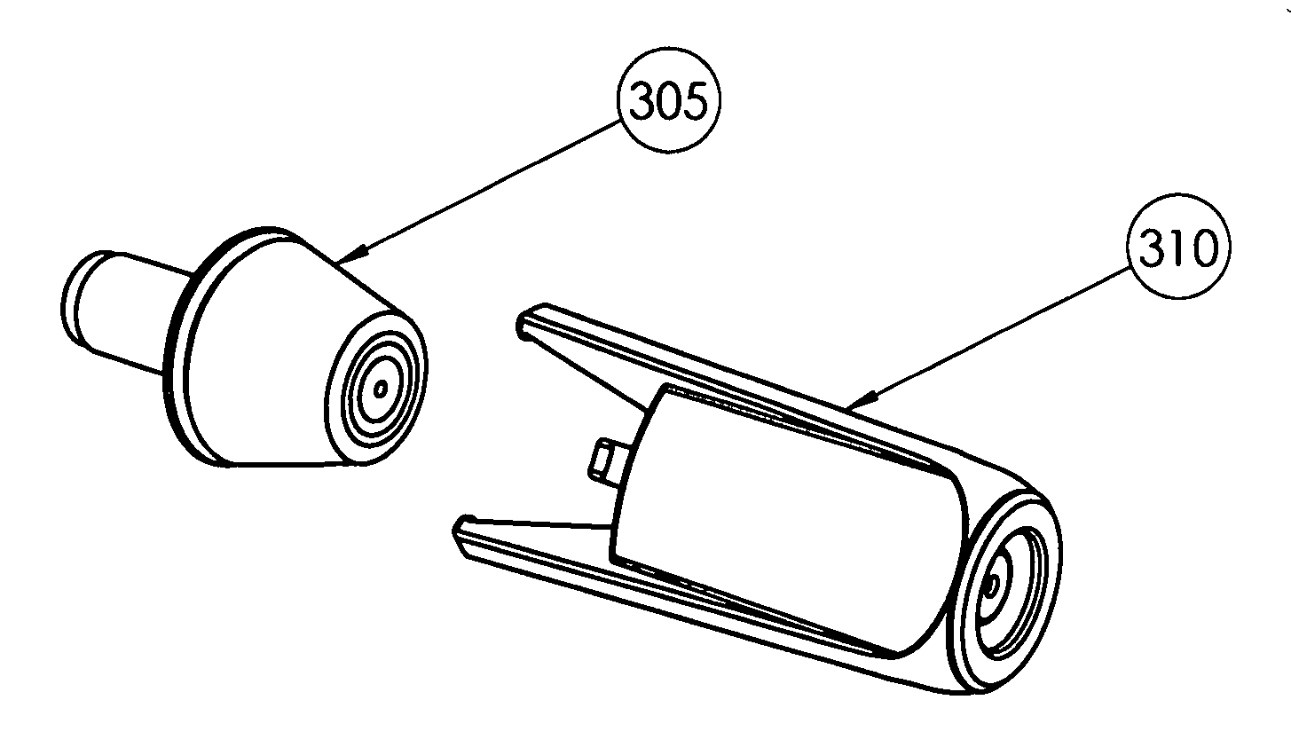
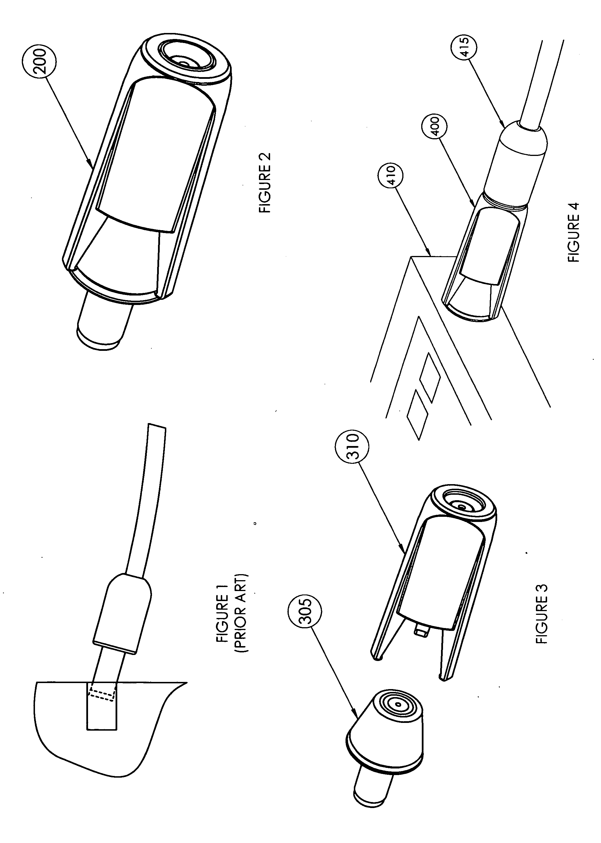
[0006]By way of introduction, the preferred embodiments described below provide a releasable connector system. In one preferred embodiment, a conically shaped plug is inserted into a laptop jack. A pronged jack is then snapped onto the conically shaped plug which makes electrical contact with the plug. A standard laptop power plug and cord is inserted into the pronged jack allowing the laptop to power on or charge.
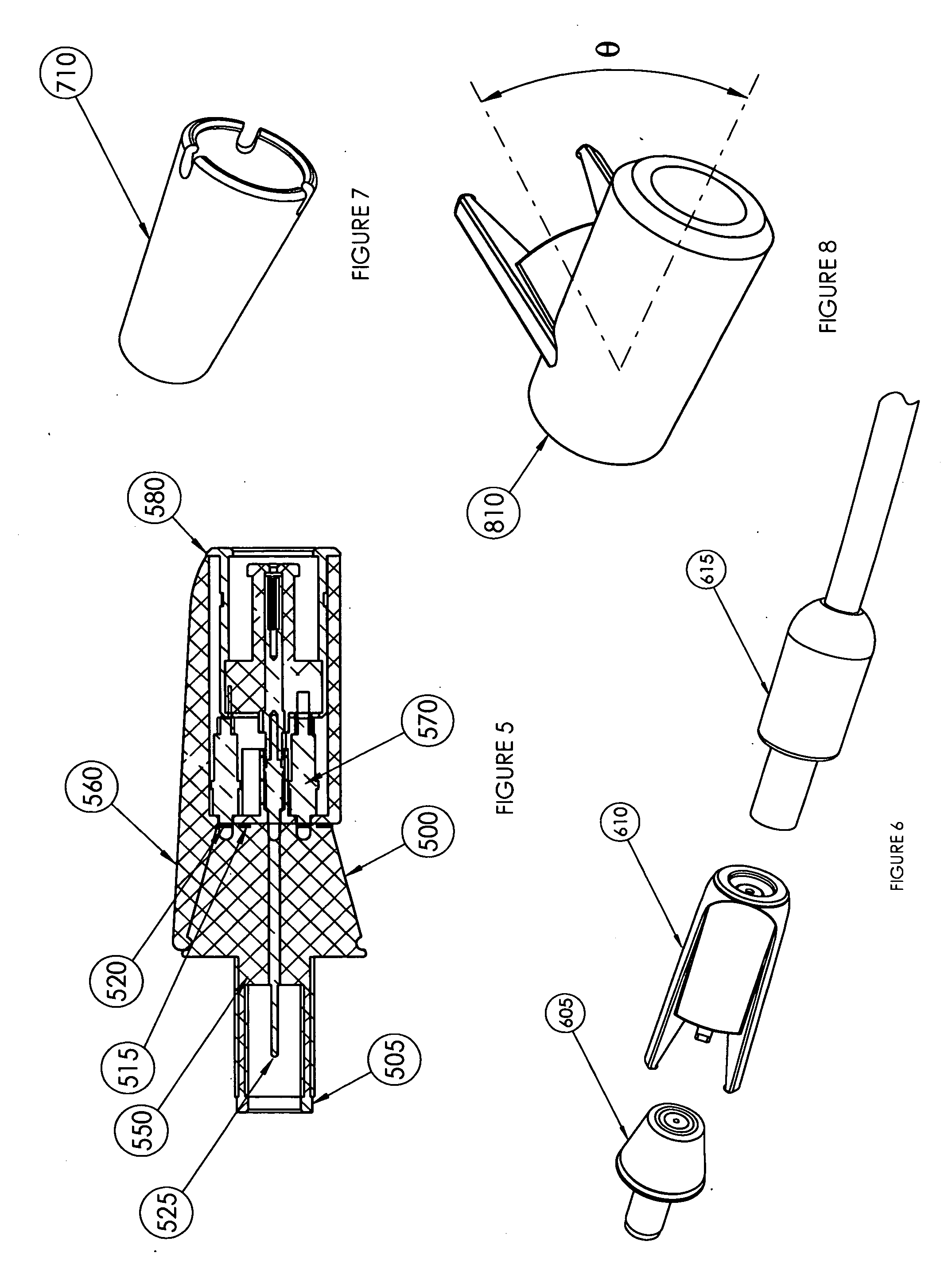
[0007]The pronged jack portion contains features that snap into a groove on the conical portion of the plug. A mating pair is established by the diameter of the groove and mating feature on the pronged jack.
[0008]The pronged elements hold the two connector parts together and are stable enough to support the weight of the power cable. The design of the pronged elements allows a non-axial force to disconnect the plug and jack without causing damage to the device connector. The design geometry allows the pronged elements to release without snagging on the plug element. The co...
PUM
 Abstract
Description
Claims
Application Information
 - R&D
- Intellectual Property
- Life Sciences
- Materials
- Tech Scout
- Unparalleled Data Quality
- Higher Quality Content
- 60% Fewer Hallucinations
Browse by: Latest US Patents, China's latest patents, Technical Efficacy Thesaurus, Application Domain, Technology Topic, Popular Technical Reports.
© 2025 PatSnap. All rights reserved.Legal|Privacy policy|Modern Slavery Act Transparency Statement|Sitemap|About US| Contact US: help@patsnap.com