Signal transmission cable with insulation piercing terminals

a technology of signal transmission cable and terminal, which is applied in the direction of contact members penetrating/cutting insulation/cable strands, coupling device connections, electrical devices, etc., can solve the problems of high crosstalk interference and adverse influence of signal integrity during digital signal transmission, so as to reduce crosstalk interference, maintain signal integrity, and reduce impedance variation

Inactive Publication Date: 2013-01-17
YES WAY ENTERPRISE CORP
View PDF1 Cites 9 Cited by
  • Summary
  • Abstract
  • Description
  • Claims
  • Application Information

AI Technical Summary

Benefits of technology

[0005]A primary object of the present invention is to provide a signal transmission cable with insulation piercing terminals that includes a plurality of conductors respectively having a bare section formed at an end thereof, so as to regulate the stub effect of the signal transmission cable and to reduce impedance variation, maintain signal integrity and lower crosstalk interference during digital signal transmission.
[0006]To achieve the above and other objects, the signal transmission cable with insulation piercing terminals according to the present invention includes a flat cable having a plurality of conductors, and a plurality of conductive terminals electrically connected to an end of the flat cable. The conductors respectively have a sheathed section, and a bare section located at an end of the sheathed section and having a length ranged b...

Problems solved by technology

However, the stubs 221 will produce parasitic capacitance and inductance effect, which will affect the high-frequency component of the digital signal, so that there is a comparably large impedance variation betwee...

Method used


Image

  • Signal transmission cable with insulation piercing terminals
  • Signal transmission cable with insulation piercing terminals
  • Signal transmission cable with insulation piercing terminals

Examples


first embodiment

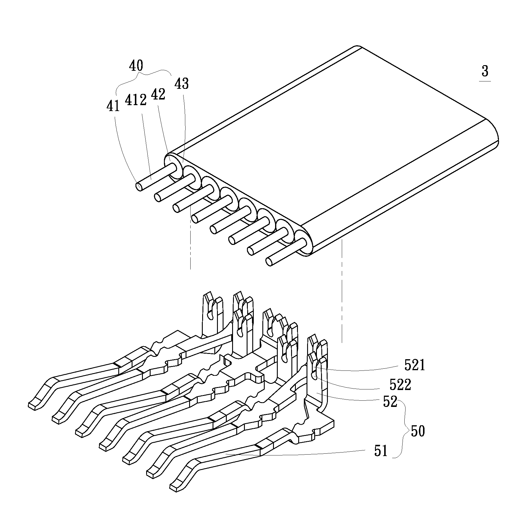
[0032]Please refer to FIGS. 2 and 3 that are exploded and assembled perspective views, respectively, of a signal transmission cable with insulation piercing terminals according to a first preferred embodiment of the present invention, and to FIG. 4 that is a sectional side view of FIG. 3. For the purpose of conciseness, the present invention is also briefly referred to as a signal transmission cable herein and is generally denoted by reference numeral 3. As shown, in the first embodiment, the signal transmission cable 3 includes a flat cable 40 and a plurality of conductive terminals 50. The flat cable 40 includes a plurality of conductors 41, each of which has a sheathed section 411 and a bare section 412 located at an end of the sheathed section 411. The sheathed sections 411 are respectively surrounded by a first sheath 42, and all the first sheaths 42 are then surrounded by a common second sheath 43. The bare section 412 has a defined length ranged between 0.01 mm and 4 mm.

[0033...

third embodiment

[0041]FIGS. 6A and 6B are exploded and assembled views, respectively, of a signal transmission cable 3 according to a third preferred embodiment of the present invention. In the third embodiment, the signal transmission cable 3 is connected to a connector 60. The connector 60 includes a seat 61 and a cover 62 correspondingly closed onto the seat 61. The seat 61 internally defines a receiving space 611 for accommodating an end of the signal transmission cable 3 having the conductive terminals 50 connected thereto. After the cover 62 is correspondingly closed onto the signal transmission cable 3 and the seat 61, the signal transmission cable 3 is securely held in the receiving space 611 with the bare sections 412 also being covered by the cover 62. In this manner, the signal transmission cable 3 and the connector 60 can be quickly and securely assembled to each other.

[0042]FIGS. 7A and 7B are assembled perspective view and fragmentary cross sectional view, respectively, of a signal tr...

fourth embodiment

[0043]The bare sections 412 in the present invention respectively have a free end being bent toward the cover 62 to form a bent section 413. Meanwhile, the cover 62 is provided on an inner side at a predetermined position corresponding to the bent sections 413 with a locating section 621. When the signal transmission cable 3 is assembled to the connector 60, the bent sections 413 of the bare sections 412 are hooked to the locating section 621 to enable further increased pull strength between the signal transmission cable 3 and the connector 60. In this manner, the signal transmission cable 3 can be secured to the connector 60, and signal integrity can be maintained and crosstalk interference can be effectively reduced during digital signal transmission.

[0044]Please refer to FIG. 8A that is an assembled perspective view of a signal transmission cable 3 according to a fifth preferred embodiment of the present invention, and to FIG. 8B that is an exploded perspective view showing the a...


PUM


Abstract

A signal transmission cable with insulation piercing terminals includes a flat cable having a plurality of conductors, and a plurality of conductive terminals electrically connected to an end of the flat cable. The conductors respectively have a sheathed section, and a bare section located at an end of the sheathed section and having a length ranged between 0.01 mm and 4 mm. The sheathed sections are respectively surrounded by a first sheath before being together surrounded by a second sheath. The conductive terminals respectively include a spring contact and a plurality of piercing sections formed at an end of the spring contact for electrically connecting to the conductors of the flat cable. The bare sections with a defined length can reduce the stub effect on a signal transmitted via the signal transmission cable to achieve better impedance matching and reduced crosstalk interference during digital signal transmission.

Description

FIELD OF THE INVENTION[0001]The present invention relates to a signal transmission cable, and more particularly to a signal transmission cable with insulation piercing terminals that includes a plurality of conductors respectively having a bare section formed at an end thereof, so as to reduce the stub effect on a digital signal being transmitted via the signal transmission cable and to achieve better impedance matching and reduced crosstalk interference during digital signal transmission.BACKGROUND OF THE INVENTION[0002]The currently available electronic devices, depending on the hardware interfaces thereof, are often provided with different flat cables and adapters. For example, some of the currently very popular transmission interfaces include USB2.0, USB3.0, SATA, and HDMI. Based on these transmission interfaces, there is developed a technique of electrically connecting a flat cable with a connector using conductive terminals that pierce through the insulating sheaths of the fla...

Claims


Application Information

Patent Timeline
IPC IPC(8): H01R4/24
CPCH01R13/2442H01R12/675
Inventor LIU, DA-YULIU, DA-YUNGLIU, TENG-LANJANG, BEN-HWA
Owner YES WAY ENTERPRISE CORP
Why Eureka
Try Eureka